
Determination of deflection of a microscope slide

a technology of deflection and microscope slide, which is applied in the field of acquisition of microscopy images, can solve the problems of insufficient solution, all or part of some images may be out of focus, and the slide loading is risky, and achieves the effect of ensuring the accuracy of image acquisition and accuracy

Active Publication Date: 2016-09-01
LEICA MICROSYSTEMS CMS GMBH
View PDF4 Cites 17 Cited by
  • Summary
  • Abstract
  • Description
  • Claims
  • Application Information

AI Technical Summary

Benefits of technology

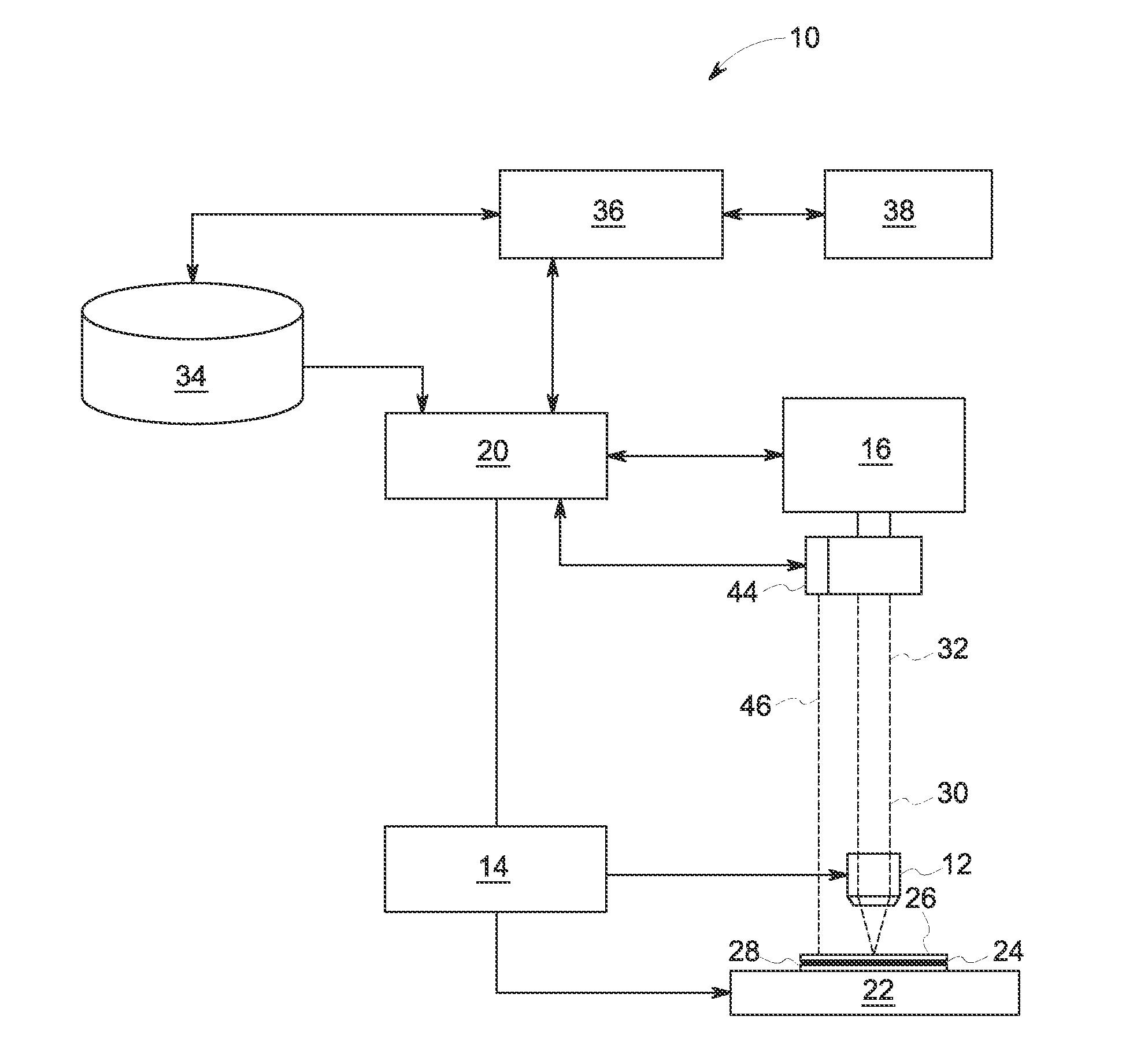
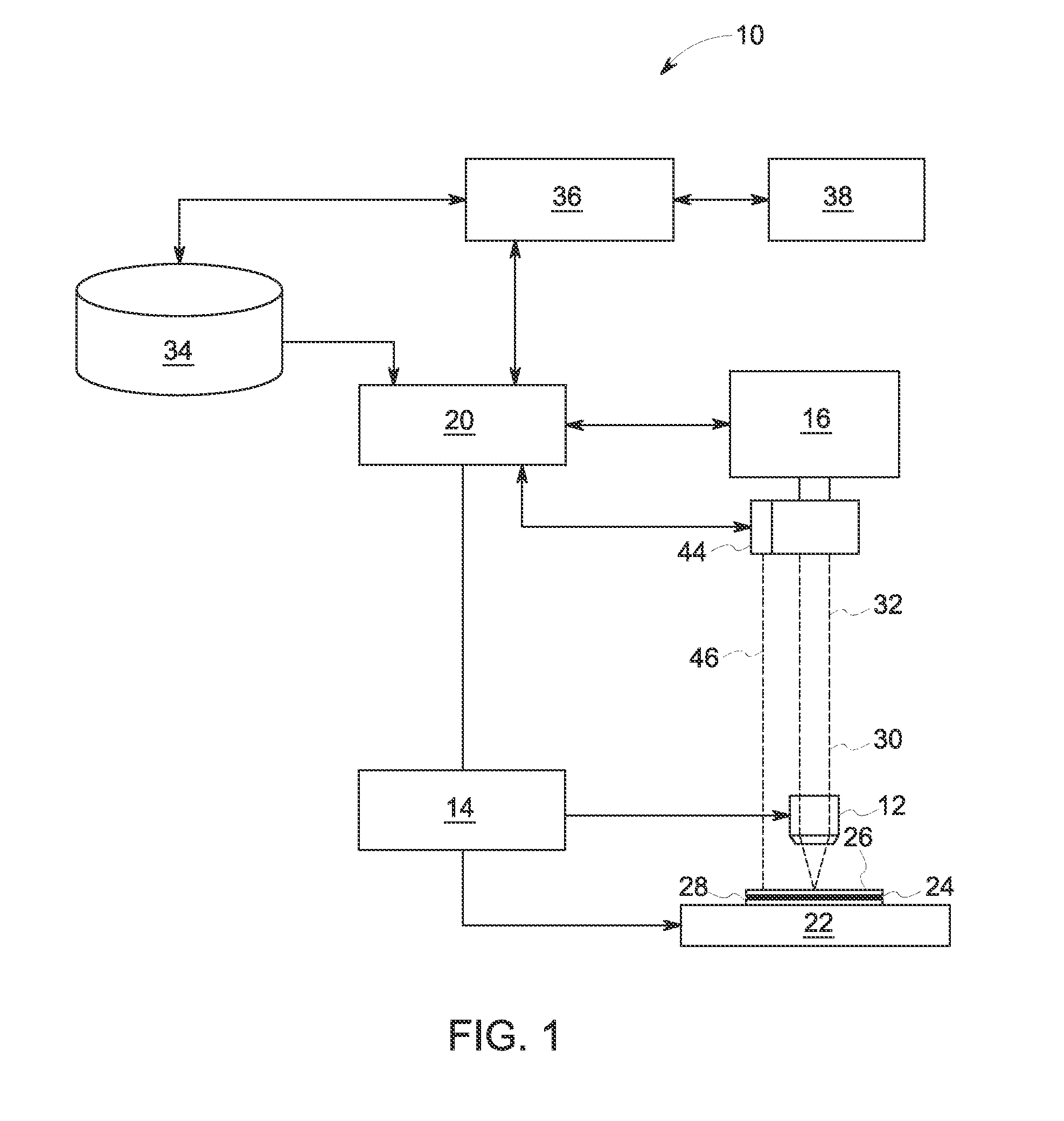
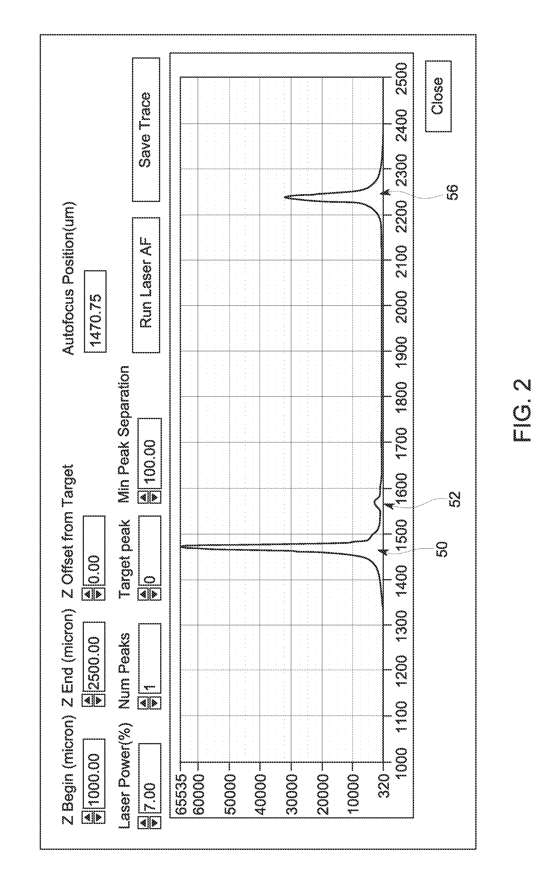
The patent text describes a method and system for assessing tilt of a slide and automatically focusing a microscope objective on a tissue sample on the slide. The system includes a laser autofocuser and a position controller that move the objective and stage relative to each other in accordance with an imaging protocol. The method involves acquiring a plurality of autofocus measurements at different fixed locations on the slide, fitting a surface to the measurements, and deriving a measure of the tilt of the slide relative to the slide holder based on the fitted surface. The technical effects include improved accuracy in assessing tilt and efficient and automated autofocalization in microscope imaging.

Problems solved by technology

With this in mind, one problem arising from microscopy imaging in general, including multiplexed approaches such as the one described, is how to calibrate (e.g., optically, geometrically, mechanically, and so forth) certain aspects of an image acquisition by a microscope.
For example, if a tissue slide is not loaded properly into a slide holder, there is a risk of tilted slide loading and possible out-of-focus images during an automated image acquisition.
In particular, when a slide is loaded into a slide holder tilted and the tilt has exceeded the focusing range of the objective for imaging, all or part of some images may be out of focus.
However, this approach only works for locations on the slide where tissue exists, and is therefore an incomplete solution.

Method used


Image

  • Determination of deflection of a microscope slide
  • Determination of deflection of a microscope slide
  • Determination of deflection of a microscope slide

Examples


Embodiment Construction

[0022]One or more specific embodiments of the present disclosure will be described below. These described embodiments are only examples of the presently disclosed techniques. Additionally, in an effort to provide a concise description of these embodiments, all features of an actual implementation may not be described in the specification. It should be appreciated that in the development of any such actual implementation, as in any engineering or design project, numerous implementation-specific decisions must be made to achieve the developers' specific goals, such as compliance with system-related and business-related constraints, which may vary from one implementation to another. Moreover, it should be appreciated that such a development effort might be complex and time consuming, but may nevertheless be a routine undertaking of design, fabrication, and manufacture for those of ordinary skill having the benefit of this disclosure.

[0023]When introducing elements of various embodiment...


PUM


Abstract

The present approach relates to the measure of the planar tilt of a slide on a microscope using an integrated auto-focuser. The tilt of the slide can be used to detect improperly loaded slides (i.e. if the slide is resting on either the cover-slip or a printed barcode), compensate for misalignment between the microscope optical axis and the slide, and reduce subsequent focusing times.

Description

BACKGROUND[0001]The subject matter disclosed herein relates to acquisition of microscopy images, such as of biological or histological samples. More particularly, the disclosed subject matter relates to the calibration and focus of microscopes used in such image acquisition protocols.[0002]Certain types of molecular pathology examinations utilize a multiplexing workflow for molecular pathology imaging. When generating images using such a multiplexing workflow, a single slice of tissue (i.e., a single sample) may be used. The multiplexing workflow allows images of the tissue sample acquired over multiple rounds of imaging to be layered, with each round of imaging being directed to a different set of biomarkers applied to the sample. Through the combination of biomarkers acquired over multiple rounds of imaging, a comprehensive view of tissue composition may be attained for the sample.[0003]By way of example, in one such approach the tissue sample is repeatedly stained and bleached du...

Claims


Application Information

Patent Timeline
Patent Type & Authority Applications(United States)
IPC IPC(8): G02B21/00G02B21/36G02B7/38
CPCG02B21/006G02B21/365G02B7/38G02B21/244
Inventor CORWIN, ALEX DAVID
Owner LEICA MICROSYSTEMS CMS GMBH
Learn More