Method and Device for Enhancing Fuel Cell Lifetime

a fuel cell and lifetime technology, applied in the field of fuel cells, can solve problems such as ocv damage and start, and achieve the effect of preventing h2 losses and increasing the durability and lifetime of fuel cells

Inactive Publication Date: 2016-09-01
ZHANG YONG +2
View PDF8 Cites 5 Cited by
  • Summary
  • Abstract
  • Description
  • Claims
  • Application Information

AI Technical Summary

Benefits of technology

[0019]It is an object of this invention to provide methods and devices to completely avoid damages caused by the OCV and the oxidizer / fuel boundary and thus to significantly increase the durability and lifetime of a fuel cell.
[0020]It is another object of this invention to prevent H2 losses during the fuel cell non-operational time period.
[0021]It is a further object of this invention to provide methods and devices to completely avoid damages caused by the OCV to the MEAs and stacks during their storage time period.

Problems solved by technology

Despite all the recent advances in reducing the impacts of the OCV and the O2 / H2 boundary via purging using N2, air, or H2, the impacts of the OCV and the O2 / H2 boundary have not been completely resolved, because for a longer non-operational time period, air from the environment will diffuse into both the anode and the cathode chambers, potentially resulting in damage due to the formation of an air / H2 boundary; and when both chambers are filled with air, the OCV damage will start; also, during the subsequent startup, an O2 / H2 boundary will form again to cause further damage.

Method used


Image

  • Method and Device for Enhancing Fuel Cell Lifetime
  • Method and Device for Enhancing Fuel Cell Lifetime
  • Method and Device for Enhancing Fuel Cell Lifetime

Examples


example 1

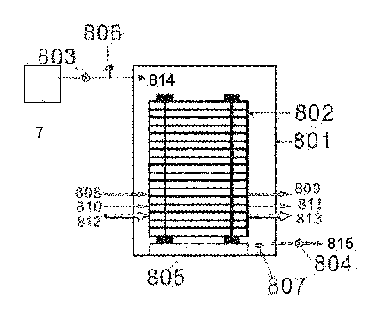
[0096]FIG. 10 illustrates a shutdown procedure when the gas-tight enclosure is already filled with H2 and the enclosure-H2-inlet-solenoid valve is in the opened state. When the fuel cell system needs not to provide power to the external load, break the electrical connection between the fuel cell system and the said load by opening the contactor or other connection device; close the stack-air-inlet solenoid valve and the stack-air-outlet solenoid valve; close the stack-H2-outlet solenoid valve and the stack-H2-inlet solenoid valve; and perform other conventional steps to let the fuel cell system into either idling or shutdown state.

[0097]In this example, the enclosure-H2-inlet-solenoid valve keeps open in the entire time period while the fuel cell system is in either operational or non-operational state. Because the enclose 801 is gas-tight, H2 concentration within the enclosure changes little in the entire process. In case that the enclosure 801 does not achieve complete gas-tight d...

example 2

[0099]FIG. 11 illustrates another shutdown procedure when the gas-tight enclosure is already filled with H2 and the enclosure-H2-inlet-solenoid valve is in the opened state. When the fuel cell system needs not to provide power to the external load, break the electrical connection between the fuel cell system and the said load by opening the contactor or other connection device; close the stack-air-inlet solenoid valve and the stack-air-outlet solenoid valve; close the stack-H2-outlet solenoid valve; and perform other conventional steps to let the fuel cell system into the non-operational state.

[0100]In the third step of this procedure only the stack-H2-outlet solenoid valve is closed. In other word, the stack-H2-inlet solenoid valve is not closed. Such an arrangement can assure that the anode chamber of the stack 802 is always filled with H2, and facilitate the diffusion of H2 from the anode to the cathode, and thus the oxygen in the cathode can be consumed faster by H2 diffusing th...

example 3

[0101]FIG. 12 illustrates a shutdown procedure when the gas-tight enclosure is filled with air during the operation of the fuel cell system. When the fuel cell system needs not to provide power to the external load, break the electrical connection between the fuel cell system and the said load by opening the contactor or other connection device; close the stack-air-inlet solenoid valve and the stack-air-outlet solenoid valve; close the stack-H2-outlet solenoid valve; open the enclosure-H2-inlet solenoid valve 803 and the enclosure-H2-outlet solenoid valve 804 after the stack voltage drops to nearly 0 V; close the enclosure-H2-outlet-solenoid valve 804 two minutes later; and perform other conventional steps to let the fuel cell system into the non-operational state.

[0102]In this example, the enclosure-H2-inlet-solenoid valve 803 and enclosure-H2-outlet-solenoid valve 804 are opened after the stack voltage drops to nearly 0 V; and enclosure-H2-outlet-solenoid valve is closed after the...


PUM

PropertyMeasurementUnit
absolute pressureaaaaaaaaaa
thicknessaaaaaaaaaa
pressureaaaaaaaaaa

Abstract

A method for enhance lifetime of fuel cells via a device includes a step of creating a H2 environment for a stack, wherein the H2 environment is composed of H2 confined within a gas-tight enclosure of the device. The device includes an enclosure-H2-inlet port, an enclosure-H2-outlet port, a stack-H2-inlet, a stack-H2-outlet, a stack-air-inlet, a stack-air-outlet, a stack-coolant-inlet, and a stack-coolant-outlet. The device prevents air from getting into the stack when the fuel cell system is in the idling or shutdown state. It solves the problems associated with the electrode damage caused by the open circuit voltage in the entire fuel cell non-operational time period and the electrode damage caused by the formation of an air/hydrogen boundary during either the startup or shutdown process. The device eliminates the damages of the open circuit voltage to either MEAs or stacks during their storage time period.

Description

CROSS REFERENCE OF RELATED APPLICATION[0001]This is a non-provisional application that claims priority to international application number PCT / CN2014 / 000091, international filing date Jan. 24, 2014, the entire contents of each of which are expressly incorporated herein by reference.NOTICE OF COPYRIGHT[0002]A portion of the disclosure of this patent document contains material which is subject to copyright protection. The copyright owner has no objection to any reproduction by anyone of the patent disclosure, as it appears in the United States Patent and Trademark Office patent files or records, but otherwise reserves all copyright rights whatsoever.BACKGROUND OF THE PRESENT INVENTION[0003]1. Field of Invention[0004]This invention relates to fuel cells, particularly to method and device to eliminate the damages to the fuel cells caused by the open circuit voltage (OCV) in the fuel cell non-operational time period and by the formation of oxidizer / fuel boundaries during the fuel cell st...

Claims


Application Information

Patent Timeline
Patent Type & Authority Applications(United States)
IPC IPC(8): H01M8/04223H01M8/04303H01M8/04746H01M4/92H01M8/241H01M8/2457H01M8/1004H01M8/04228H01M8/04955
CPCH01M8/04231H01M8/04228H01M8/04303H01M8/04753H01M8/04955H01M8/241H01M8/2457H01M8/1004H01M4/926H01M2008/1095H01M2250/20H01M8/04225H01M8/04089H01M8/04238H01M8/0444H01M8/04746H01M8/2475Y02E60/50H01M8/043Y02T90/40
Inventor ZHANG, YONGMA, WEIQI, ZHIGANG
Owner ZHANG YONG
Why Eureka
Try Eureka