Unmanned Aerial Delivery System

a technology of unmanned aerial vehicles and delivery systems, applied in the direction of vehicle position/course/altitude control, process and machine control, instruments, etc., can solve the problems of high cost and time consumption of repeat delivery times, inefficient road transportation networks, and large urban areas. , to achieve the effect of enhancing system logistics, reducing charging time, and increasing the range of delivery/pickup routes

Active Publication Date: 2016-09-08
MARTIN JOSEPH
View PDF13 Cites 165 Cited by
  • Summary
  • Abstract
  • Description
  • Claims
  • Application Information

AI Technical Summary

Benefits of technology

[0022]In another embodiment, the docking end of the elevated structure may also include a power supply apparatus that replenishes the power source on the UAV. The power supply apparatus can include an AC power source, a 12 volt DC outlet, a solar power source, and a fuel tank or other power sources currently known in the art. Those skilled in the art will recognize that a power supply apparatus, such as a battery charger for a rechargeable battery in the UAV also monitors battery voltage, current flow, and battery temperature to minimize charging time. In some embodiments, the system comprises at least one recharging point, separate from the initiation point or delivery points, where the UAV may replenish its power source. The recharging po

Problems solved by technology

Also currently there exists a problem with parcel delivery method such as UPS for packages that need a signature which often involves confirmation of delivery of a package or item where human beings interaction is necessary to accept delivery which often requires repeat delivery times which are costly and time-consuming.
In these high-density urban environments demand on ground transportation infrastructure has increased and continues to increase to the point that many metropolitan areas are heavily congested and road transportation networks are very inefficient.
Currently, electrically powered UAVs are limited in range and duration by the size and weight of the batteries or other power sour

Method used


Image

  • Unmanned Aerial Delivery System
  • Unmanned Aerial Delivery System
  • Unmanned Aerial Delivery System

Examples


Embodiment Construction

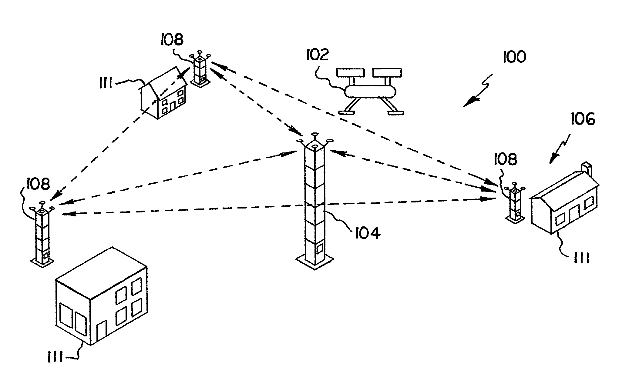
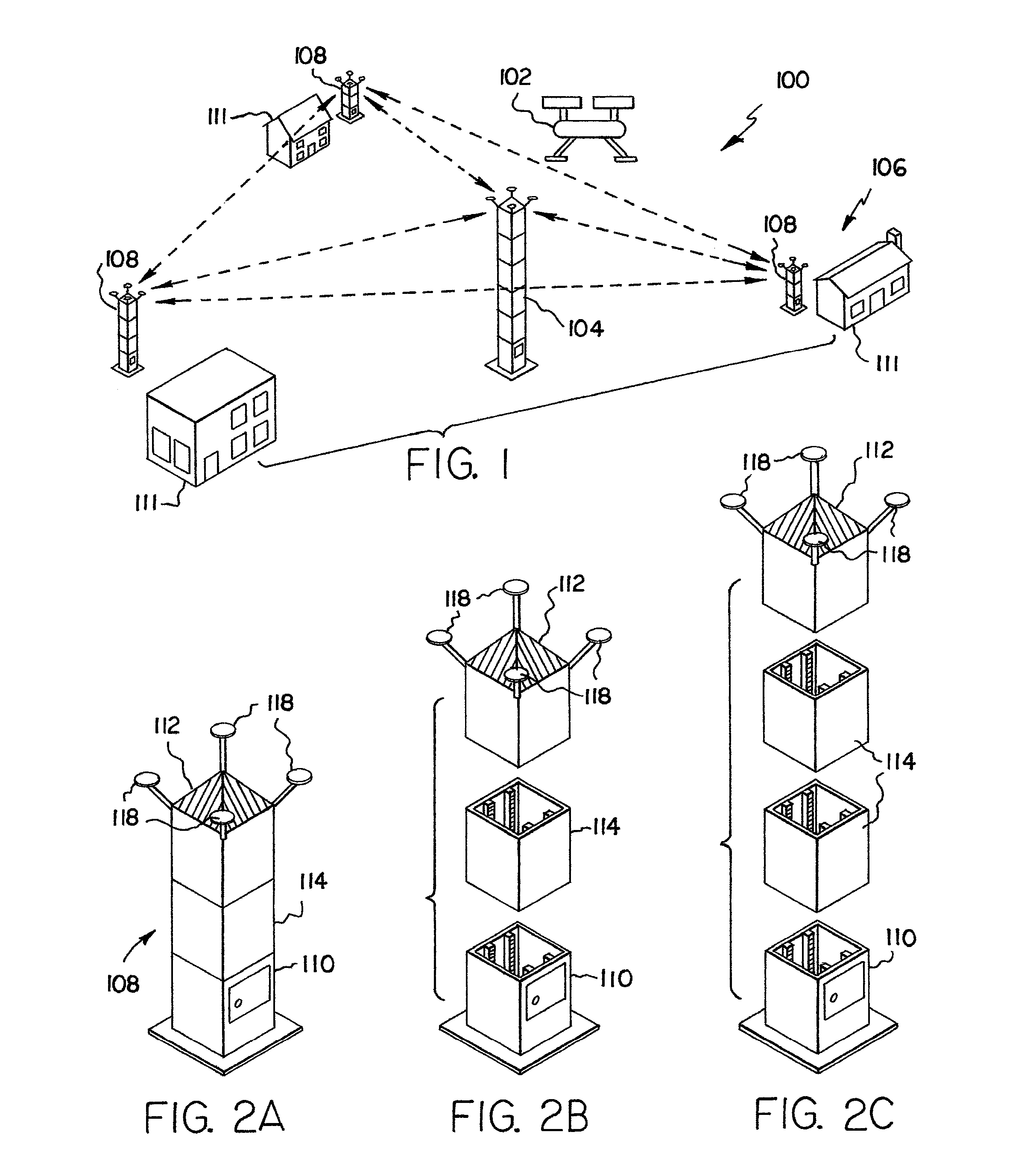
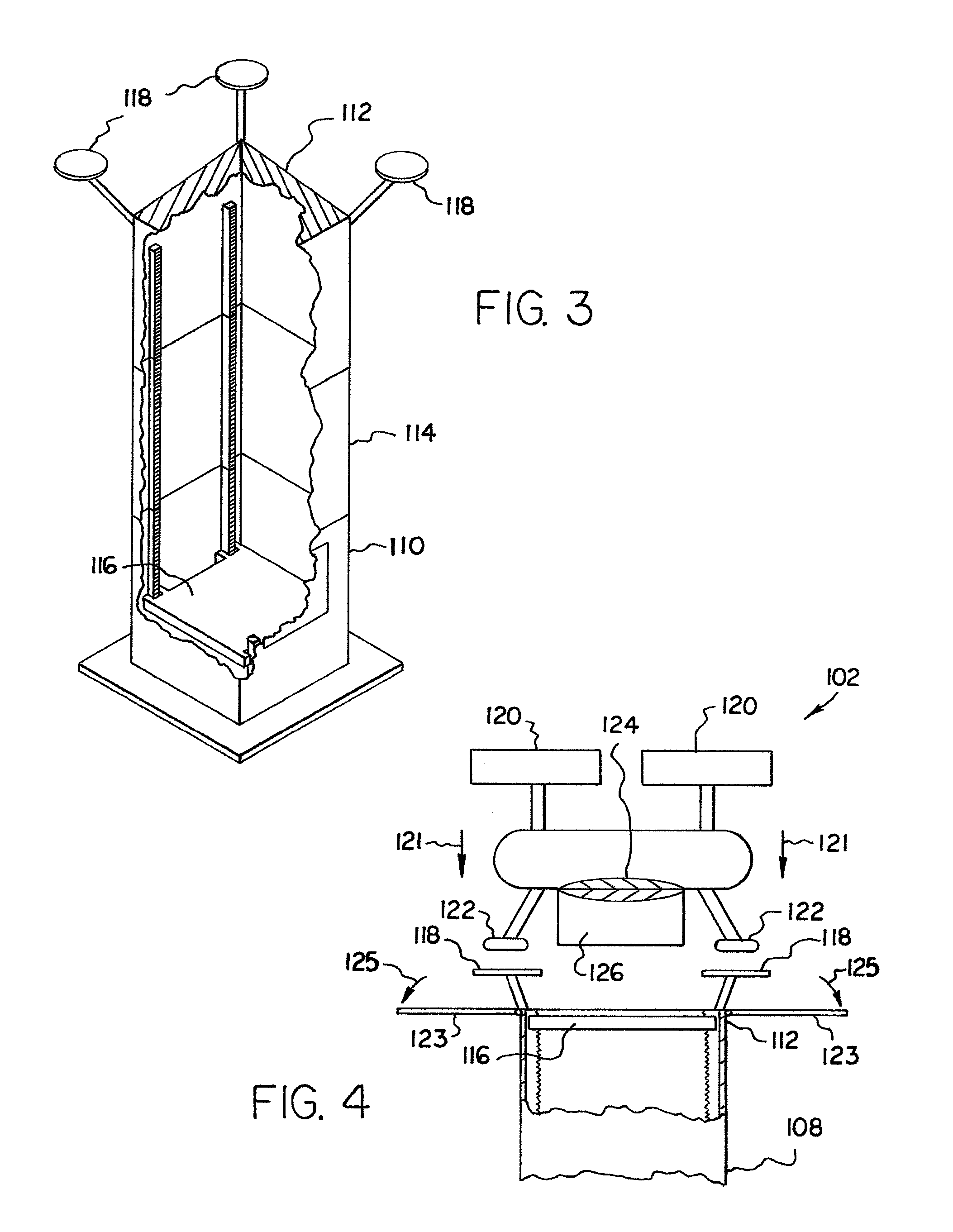
[0057]The following detailed description is merely exemplary in nature and is not intended to limit the described embodiments or the application and uses of the described embodiments. As used herein, the word “exemplary” or “illustrative” means “serving as an example, instance, or illustration.” Any implementation described herein as “exemplary” or “illustrative” is not necessarily to be construed as preferred or advantageous over other implementations. All of the implementations described below are exemplary implementations provided to enable persons skilled in the art to make or use the embodiments of the disclosure and are not intended to limit the scope of the disclosure, which is defined by the claims. For purposes of description herein, the terms “upper,”“lower,”“left,”“rear,”“right,”“front,”“vertical,”“horizontal,” and derivatives thereof shall relate to the invention as oriented in FIG. 1. Furthermore, there is no intention to be bound by any expressed or implied theory pres...


PUM


Abstract

An unmanned aerial vehicle delivery system utilizes an unmanned aerial vehicle (UAV) to deliver packages between an initiation point and multiple delivery points at a raised elevation. The UAV flies between points in an organized manner, using logistical, maintenance and safety software, commands from a delivery organization, and guidance tools to coordinate deliveries. One advantage of the system is that the UAV engages the delivery points at a raised elevation, rather than the ground level. The UAV docks through an elevated structure at the delivery point for delivering the package and replenishing a power source. The package is conveyed from a docking end and through a central shaft of the elevated structure by means of an elevator. The package then travels to a lower structure, such as a house or office, for pickup. After completion of the delivery, the UAV replenishes its power source and/or continues on the delivery route.

Description

FIELD OF THE INVENTION[0001]The present invention relates generally to an unmanned aerial vehicle delivery system. More so, an unmanned aerial vehicle delivery system provides an unmanned aerial vehicle that docks with an elevated structure at a delivery point to deliver or receive a package(s) and recharge or replenish a power source.BACKGROUND OF THE INVENTION[0002]The following background information may present examples of specific aspects of the prior art (e.g., without limitation, approaches, facts, or common wisdom) that, while expected to be helpful to further educate the reader as to additional aspects of the prior art, is not to be construed as limiting the present invention, or any embodiments thereof, to anything stated or implied therein or inferred thereupon.[0003]The following is an example of a specific aspect in the prior art that, while expected to be helpful to further educate the reader as to additional aspects of the prior art, is not to be construed as limiting...

Claims


Application Information

Patent Timeline
IPC IPC(8): B64F1/00B64D1/10G05D1/10B64C39/02
CPCB64F1/00B64C39/024B64C2201/128G05D1/101B64C2201/024B64D1/10A47G29/14B64U50/34B64U2101/60B64U10/13B64U50/19
Inventor MARTIN, JOSEPH
Owner MARTIN JOSEPH
Why Eureka
Try Eureka