Implantable medical device with contactless power transfer housing

a medical device and power transfer technology, applied in the field of implantable medical devices, can solve the problems of large challenge for many researchers, the size of an implanted device directly affecting the comfort of patients, so as to minimize surgery and subsequent treatments, optimize the transcutaneous magnetic coupling, and minimize charging time

Inactive Publication Date: 2005-12-29
AHN IN +2
View PDF9 Cites 254 Cited by
  • Summary
  • Abstract
  • Description
  • Claims
  • Application Information

AI Technical Summary

Benefits of technology

[0013] It is another object to provide a transcutaneous power transmission apparatus for use in an implantable medical device that is small and compact, and can be implanted with the medical device, thereby minimizing surgery and subsequent treatments.
[0014] It is another object to provide a transcutaneous power transmission apparatus for use in an implantable medical device that optimizes the transcutaneous magnetic coupling to minimize charging time.
[0015] According to the present invention, the above-described and other objects are accomplished by providing an apparatus for providing power to an implantable medical device comprising a primary side circuit for transmitting power in the form of magnetic flux; and a secondary side circuit integral to the implantable medical device for receiving the power transmitted from the primary side circuit and for providing the received power to recharge a battery in the implantable medical device, wherein the primary and secondary side circuits are not physically coupled. A variety of attachment configurations are disclosed for attaching and shielding the secondary circuit directly onto the housing of the implantable medical device, inclusive of flexible printed circuit coils and wire coils recessed into helical notches. The system can be utilized for various implantable medical devices that requires electrical power, such as an artificial heart, a pacemaker, an implantable cardiverter defibrillator, a neurostimulator, a GI stimulator, an implantable drug infusion pump, a bone growth stimulation device, and many other devices. The system improves the power transmission coupling such that sufficient electric power can be transmitted to the medical device repeatedly without having to take the implanted medical device out of the human body. Further, since charging is more efficient and the secondary coils are integral to the implant housing the size of the battery can be reduced, thereby reducing the overall size of the implanted medical device. Moreover, the secondary coil(s) conform to the implant housing and are hermetically sealed to be non-obtrusive, non-corrosive and medically safe.

Problems solved by technology

The most pressing need for further technological advances lies in the size and weight of implanted devices, and this remains the major challenge for many researchers.
The size of an implanted device directly affects the comfort of the patient.
Particularly, if an implant is large it will require that much large opening in the living body either to insert or remove it, possibly causing an excessive bleeding and increasing vulnerability to infection during the implantation.
However, batteries have a limited lifespan and must be replaced periodically.
The replacement also requires a surgical operation to make an opening in the body, which is very inconvenient to and can be dangerous for some patients.
Implanting such a large coil adversely affects the patient's condition.
In addition, a large coil inserted into a human body could cause damages to the body.
For magnetic flux supplied from outside of a human body to reach the charger, the charger cannot be enclosed in a metal case, which imposes restrictions on the design of the implanted device.
Since ferromagnetic core surrounded by a coil is used as a component of a secondary transformer, it is bulky and vulnerable to impact from outside.
None of the foregoing nor any known contactless battery charging systems are well-adapted for incorporation directly in / on the housings of existing implantable medical devices, rather than at remote locations.
This is because existing designs are too bulky and unsuitable for implantation, are too prone to oxidation once implanted (and to poisoning the patient), are too inefficient for practical charging, or are simply incompatible with the materials of most implantable medical devices.

Method used


Image

  • Implantable medical device with contactless power transfer housing
  • Implantable medical device with contactless power transfer housing
  • Implantable medical device with contactless power transfer housing

Examples


Embodiment Construction

[0029] The present invention is a contactless power transfer system for an implantable medical device, which includes a primary recharging unit located outside the human body and a contactless power transfer housing forming a portion of the implantable medical device that is implanted inside the human body. A number of embodiments of the present invention will now be described in details with reference to the accompanying drawings.

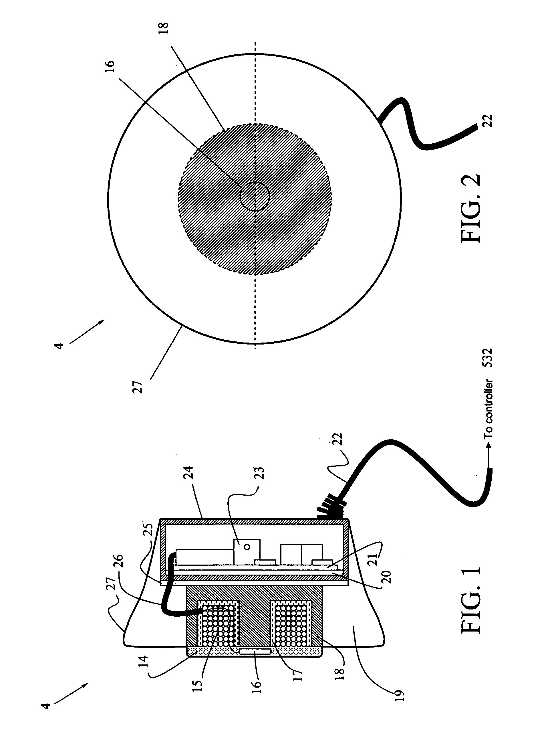
[0030]FIG. 1 is a side cut-away view, and FIG. 2 is a front view of the primary recharging unit 4, which generally comprises a toroid-shaped housing 27 with charging coils 15 on one side, and circuit components 23 on the other side that are connectable by power cable 22 to a controller (not shown) for controlled application of recharging power. The controller can be located either inside or outside of the primary recharging unit. The advantage of including the controller inside is minimizing the unit. Furthermore, the primary recharging unit can include s...


PUM

PropertyMeasurementUnit
frequencyaaaaaaaaaa
magnetic fluxaaaaaaaaaa
ferromagneticaaaaaaaaaa

Abstract

A transcutaneous recharging system for providing power to an implantable medical device comprises a primary side circuit for transmitting power in the form of magnetic flux; and a secondary side circuit integral to the implantable medical device for receiving the power transmitted from the primary side circuit and for providing the received power to recharge a battery in the implantable medical device, wherein the primary and secondary side circuits are not physically coupled. A variety of attachment configurations are disclosed for attaching and shielding the secondary circuit directly onto the housing of the implantable medical device, inclusive of flexible printed circuit coils and wire coils recessed into helical notches.

Description

CROSS-REFERENCE TO RELATED APPLICATIONS [0001] The present application is a continuation-in-part of U.S. Application Serial No. 949612, filed Sep. 12, 2001, which in turn derives priority from Korean Application Serial No. KR 2001-28347 filed May 23, 2001. The aforesaid applications are commonly owned by the named inventors.BACKGROUND OF THE INVENTION [0002] 1. Field of the Invention [0003] The present invention relates to implantable medical devices such as pacemakers and defibrillators and, more particularly, to an improved rechargeable power supply configuration including a remote primary circuit for contactless charging, and a housing design for the implantable medical device that incorporates a non-contact secondary circuit for charging by the remote primary circuit. [0004] 2. Description of the Background [0005] It is forecast that the US market for implantable medical devices will grow 10.9% per year through 2007, to nearly $24.4 billion. The growth leaders are anticipated to...

Claims


Application Information

Patent Timeline
Patent Type & Authority Applications(United States)
IPC IPC(8): A61F2/48A61N1/00A61N1/08A61N1/378H01F38/14H02J17/00
CPCA61N1/3787A61N1/08A61F2/48
Inventor AHN, TAE YOUNGKIM, BYUNG JOONCHANIL, MOON
Owner AHN IN
Why Eureka
Try Eureka