High-G Shock Testing Machine

a shock testing machine and high-g technology, applied in the direction of structural/machine measurement, material strength using single impulsive force, instruments, etc., can solve the problem of high cost of both testing methods, increased complexity of axial as well as lateral and bending shock loading combinations, and increased difficulty in adjusting the load

Active Publication Date: 2016-09-08
OMNITEK PARTNERS LLC
View PDF10 Cites 17 Cited by
  • Summary
  • Abstract
  • Description
  • Claims
  • Application Information

AI Technical Summary

Benefits of technology

[0011]It is also appreciated that practical test considerations impose additional requirements beyond the required multi-axial acceleration / duration performance. Most tests call for more sensor channels than are recordable in an onboard recording system. In these instances, a nearly-stationary (i.e., “pseudo-static”) test article or systems in which the test article undergoes limited and highly controlled resulting displacements that would allow the use of the desired number of sensor channels through direct cable harnesses, onboard recording systems and / or ultra-high speed RF or optical wireless communications. Another benefit of such shock testing systems is that off-board instrumentation is able to collect more channels of data with higher precision and sampling rates. One example of a pseudo-static testing is reverse ballistics where a target is propelled into a stationary and fully instrumented “Unit Under Test” (UUT).

Problems solved by technology

Similar but more complex combinations of axial as well as lateral and bending shock loadings are experienced by air dropped weapons as they impact the target, particularly when the weapon is rocket assisted to achieve high impact velocities and when the target structure is highly heterogeneous, such as reinforced concrete or soil with large rock content.
However, the corresponding change in velocity typically requires ballistic or operational testing.
Both testing methods are extremely costly, personnel intensive, and introduce both technical and safety risks.
Currently, there is no one shock testing apparatus that can shock test aircraft components to accommodate the varying shock testing requirements for aircraft components, if at all.
Thus, the industry resorts to building specialized shock testing machines or using computer simulation for shock testing, methods which are expensive and / or inaccurate.
Current shock testing machines in the consumer electronics area are either very simple drop testing from heights or pneumatic shock machines, both of which are inaccurate and their repeatability is unreliable.
Like other shock testing machinery currently available in the areas of commercial aircraft and consumer electronics, the shock testing of automobile components are inaccurate, their repeatability is unreliable and they can also be relatively expensive.

Method used


Image

  • High-G Shock Testing Machine
  • High-G Shock Testing Machine
  • High-G Shock Testing Machine

Examples


second embodiment

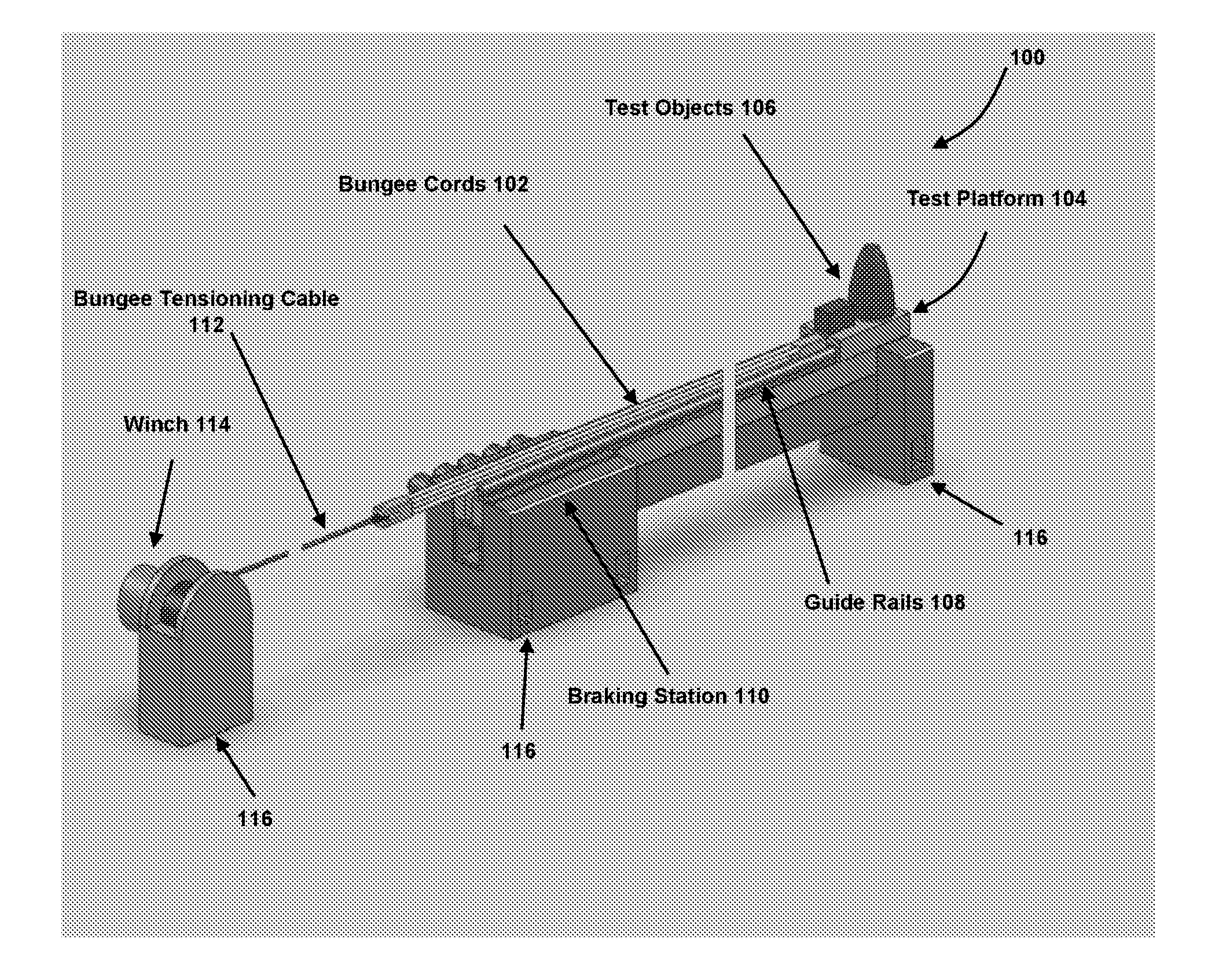
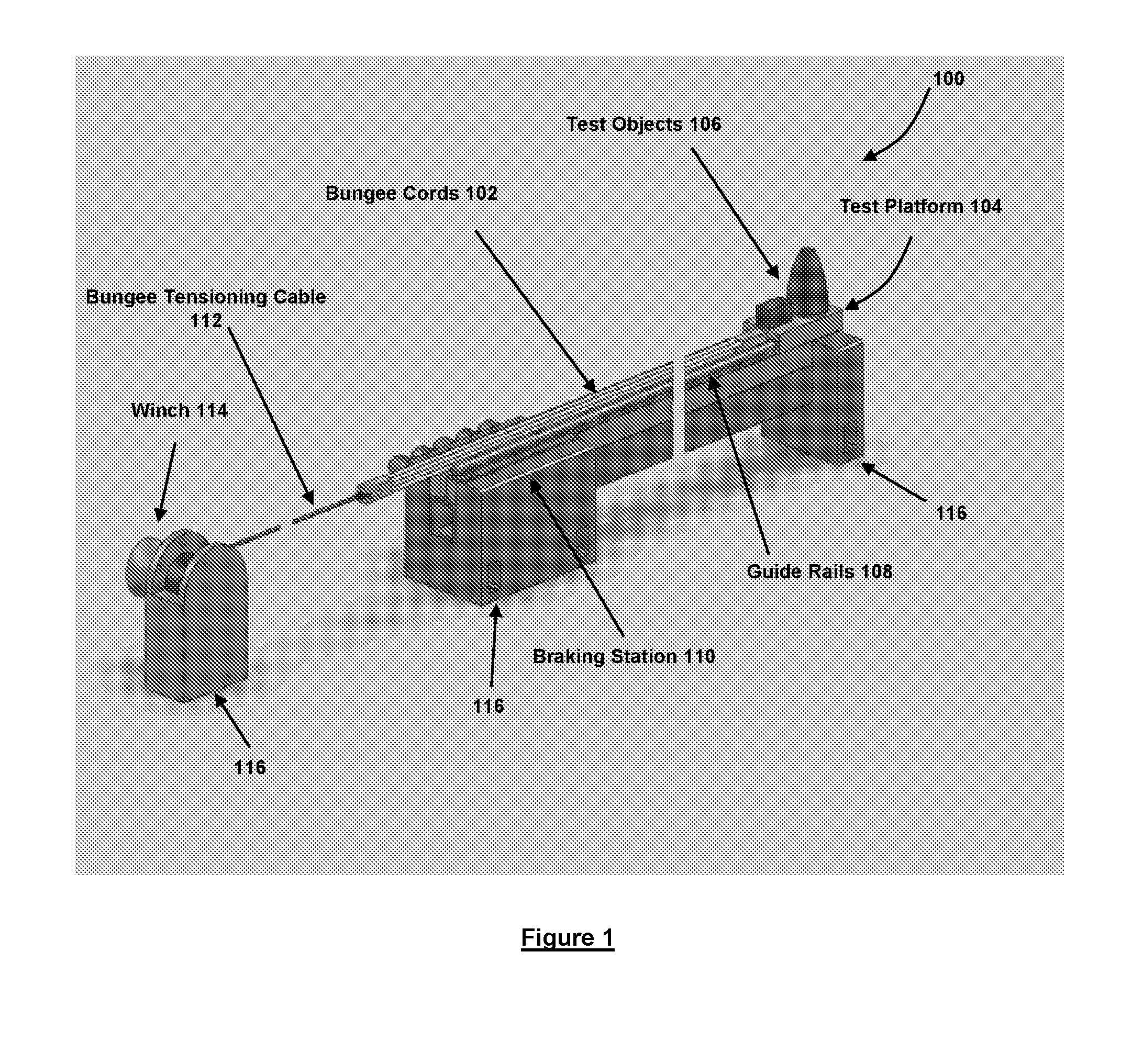
[0048]shock and shock / tail-slap testing machines are for applying short duration and high acceleration / deceleration pulses, such as of over ±10,000 g over durations of e.g., over 5 msec. These shock loading machine concepts can apply one or a combination of shock loading pulses to the article being tested, such as an ordinance, in axial and lateral directions to simulate almost any shock loading events, including tail slap, where large lateral accelerations / decelerations are introduced due to the bending and rebound in the lateral direction. For purposes of this disclosure, “tail-slap” means a shock loading event in a direction perpendicular to its intended motion, such intended motion being in a direction of penetration with regard to an ordinance. For other articles being testing, the term shock loading event is merely in a direction created by the machine with regard to an orientation of the article being tested in the machine.

[0049]The first embodiment of shock and shock / tail-sl...

first embodiment

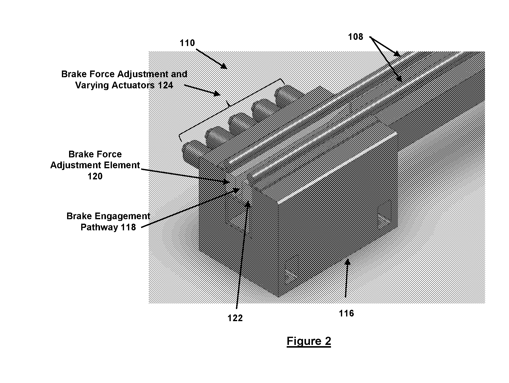
[0050]The shock testing machine of the first embodiment is shown in FIG. 1, generally referred to by reference numeral 100. In FIG. 1, the breaks on the left and right of the machine are used to denote a long length of the components being broken. In this design, the machine 100 is laid down horizontally to allow the use of longer test platform travel and the use of longer length bungee cords 102 to provide large accelerating forces to the test platform 104 over the entire range of its travel. The test objects 106 are mounted over the test platform 104 using mounting means specific to the type of object and the testing required. The test platform 104 is accelerated on one or more guide rails 108 towards a braking station 110 having braking elements (described below) by locking the test platform 104 from movement, tensioning the bungee cords 102 with the bungee tensioning cable 112 and winch 114 and then releasing the test platform 102 to allow the tension in the bungee cord(s) 102 t...


PUM

PropertyMeasurementUnit
diameteraaaaaaaaaa
mass M1aaaaaaaaaa
mass levelsaaaaaaaaaa

Abstract

A shock testing machine including: a test platform upon which one or more objects to be tested are mounted; one or more rails upon which the test platform is movable in a longitudinal direction; and a braking station for retarding a relative motion between the test platform and the braking station, wherein the test platform and the braking station include at least one portion interfering with the relative motion of the test platform and the braking station such that relative movement of the test platform and the braking station past the at least one portion produces a shock lateral to the longitudinal direction.

Description

CROSS REFERENCE TO RELATED APPLICATIONS[0001]This application claims benefit to U.S. Provisional Application No. 62 / 129,791 filed on Mar. 7, 2015, the contents of which is incorporated herein by reference.BACKGROUND[0002]1. Field[0003]The present invention relates generally to high-G shock testing machines, and more particularly to low-cost, reusable, “pseudo-static” testing machines and methods capable of imposing high acceleration and deceleration (>±10,000 g), opposing loads to a large (10-100+ lbs.) payload that are sustained over long durations (>5 msec). Such machine would provide the means for testing ordnance and commercial products / components under multi-axial loading, which includes both bending and shear moments. This includes the most extreme example of such events, namely “tail slap”, where large lateral accelerations are introduced due to the bending and rebound of the product / component in the lateral direction, e.g., in the case of ordnance, perpendicular to the...

Claims


Application Information

Patent Timeline
Patent Type & Authority Applications(United States)
IPC IPC(8): G01M7/08G01N3/307
CPCG01N3/307G01M7/08G01N3/31
Inventor RASTEGAR, JAHANGIR SFISCHER, JACQUESFENG, DAKE
Owner OMNITEK PARTNERS LLC
Why Eureka
Try Eureka