Side view downhole camera and lighting apparatus and method

a technology of lighting apparatus and camera, which is applied in the field of side view downhole camera and associated lighting system, can solve the problems of increasing the problems of existing light source system, all conventional means for downhole illumination suffer from a number of significant limitations, and the wellbores contain little or no existing source of ambient or available light, so as to strengthen the overall stability of the camera assembly, protect the camera from scarring, and significantly illuminate the

Inactive Publication Date: 2016-09-08
ABRADO
View PDF3 Cites 25 Cited by
  • Summary
  • Abstract
  • Description
  • Claims
  • Application Information

AI Technical Summary

Benefits of technology

[0009]A significant advantage of the present invention includes the ability to significantly illuminate a portion of a wellbore environment within a field of view of a camera having a side viewport. Illumination of acquired data (such as, for example, video or other visual images) is achieved through use of a light tube positioned near a viewport, thereby permitting transmission of light from a light source through a translucent or transparent material, which, in turn, emits light into a surrounding wellbore. It is to be observed that said light transmitting and / or diffusing material is described herein primarily as being translucent; however, depending on anticipated wellbore fluids and / or other conditions, in certain applications said material may be transparent rather than translucent.
[0010]A light source, such as a light emitting diode (“LED”), is positioned near (embedded, abutted, or positioned within close proximity to) a substantially cylindrical and substantially translucent material. Light generated by said source is diffused and emitted by said translucent material in a substantially 360 degree pattern within a wellbore, thereby illuminating a portion of said wellbore. Such translucent material may be positioned above or below a camera having a side-view viewport, while said viewport may be selectively rotated 360 degrees by a rotating motor positioned within said camera assembly.
[0011]In a preferred embodiment, translucent material is housed within a “cage” to provide protection from scarring and to reinforce the overall stability of the camera assembly. “Cutouts” or gaps are beneficially provided in the cage design to allow for the emission of light into the surrounding wellbore.
[0012]The camera assembly of the present invention can be lowered within a wellbore, deployed to a desired location within said wellbore, and thereafter retrieved from said wellbore. Although jointed or continuous pipe or other tubular goods can be used to convey such camera assembly in and out of wellbores, it is typically more operationally efficient and cost-effective to utilize flexible wireline or cable to convey such camera systems in such wellbores.
[0013]In such cases, a sufficient length of wireline or cable is maintained on a spool or drum at the earth's surface near the upper opening of a wellbore. The distal or leading end of said wireline is connected to the camera assembly of the present invention. Said leading end (and any attached tools) are vertically aligned over the upper opening of a wellbore and suspended in place using an arrangement of beneficially positioned sheaves or pulleys. Said wireline and any attached tools can then be conveyed into a wellbore by unspooling said wireline from said spool, manipulated within said wellbore, and then retrieved from said well by re-winding said wireline on said spool.
[0014]Generally, such wireline can comprise conductive electric line or “E-line” that permits the transmission of electrical charges and / or data through said wireline, or non-conductive “slickline” that does not permit such transmission of data or electrical charges. Either type of wireline can be used to convey the camera assembly of the present invention in and out of wellbores, and to obtain visual images of wellbore environments. However, only electric line can be used to convey electrical charges and data to and from a downhole camera assembly to the earth's surface; slick line does not have this capability.

Problems solved by technology

However, most wellbores contain little or no existing source of ambient or available light.
However, all conventional means for downhole illumination suffer from a number of significant limitations.
In particular, as the size of a surrounding wellbore diameter is decreased, problems with existing light source systems typically increase.
Although some conventional downhole camera systems do permit lateral viewing—that is, viewing in a direction that is substantially perpendicular to the longitudinal axis of a wellbore—lighting / illumination of such lateral areas can be particularly challenging.
Width restrictions within a wellbore (i.e., the available “side-to-side” space within the internal diameter of a wellbore) are significantly limited, particularly when such available space must be shared with camera components and / or other equipment.
Because it is difficult to illuminate a relatively narrow wellbore having limited space with a narrow tool, conventional downhole camera systems typically utilize direct lighting techniques, such as placing LEDs close or next to a side-viewing camera lens.
However, such direct lighting typically results in problems such as an increase in shadows and dark spots in video captured.

Method used


Image

  • Side view downhole camera and lighting apparatus and method
  • Side view downhole camera and lighting apparatus and method
  • Side view downhole camera and lighting apparatus and method

Examples


Embodiment Construction

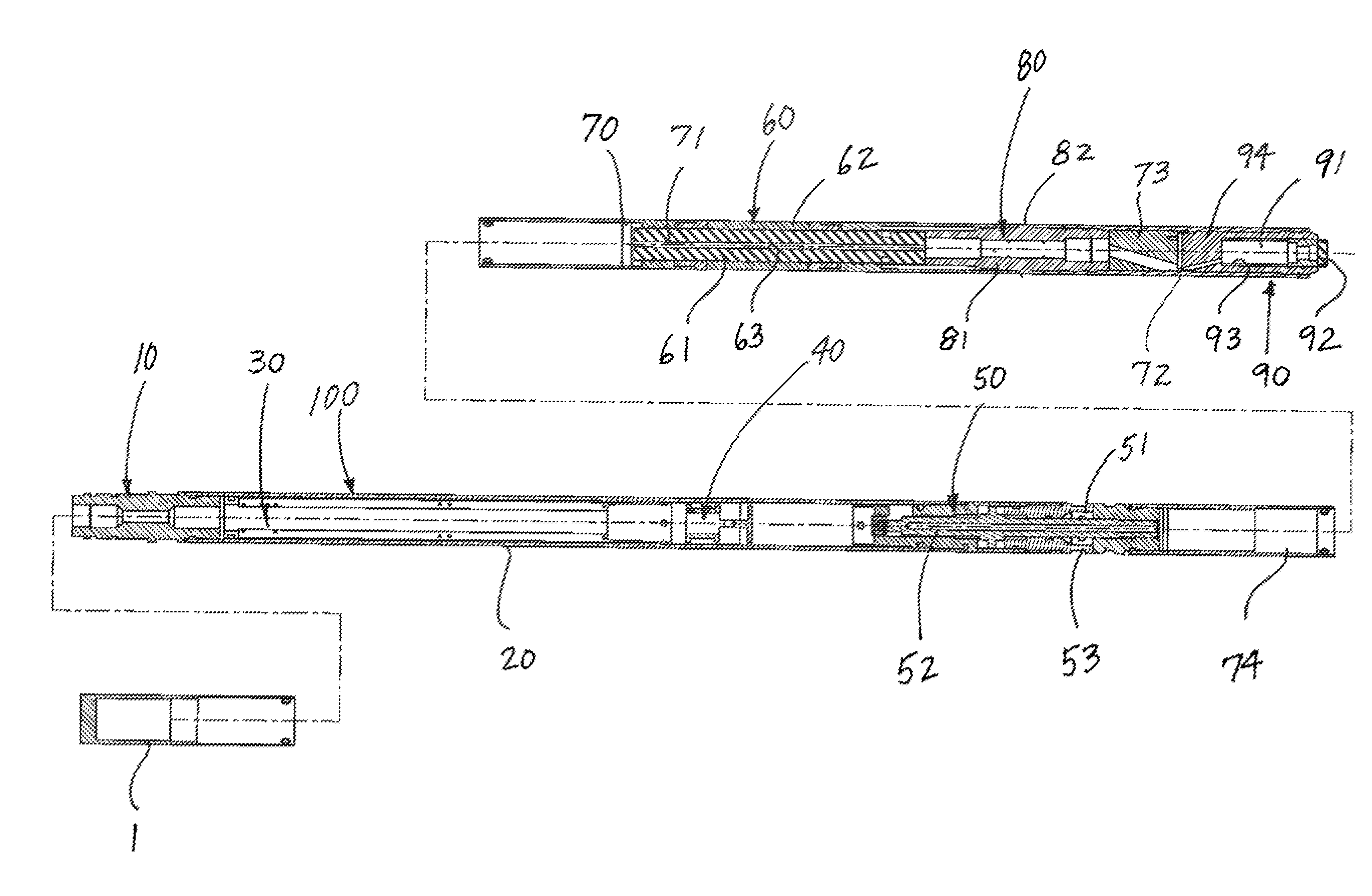
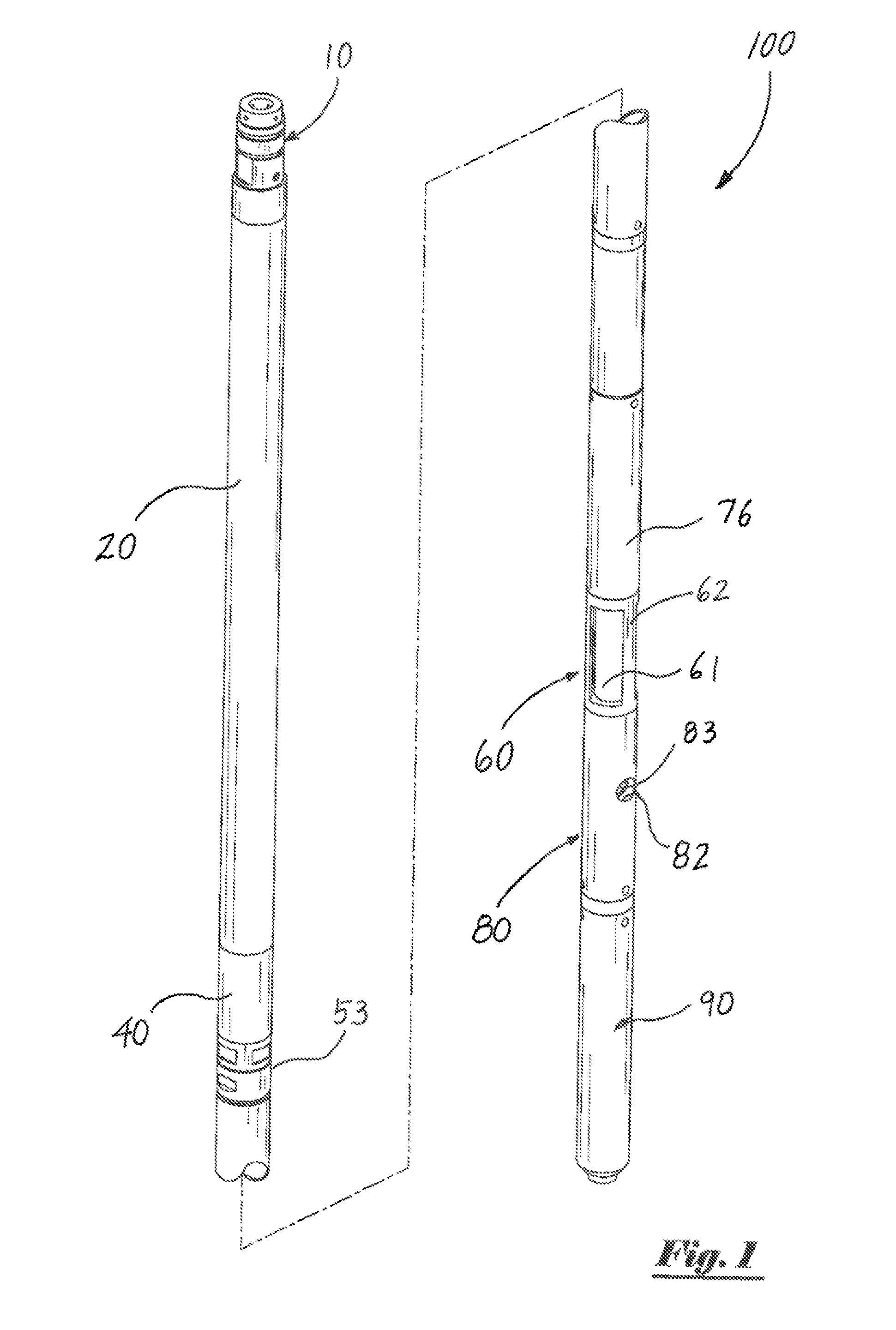
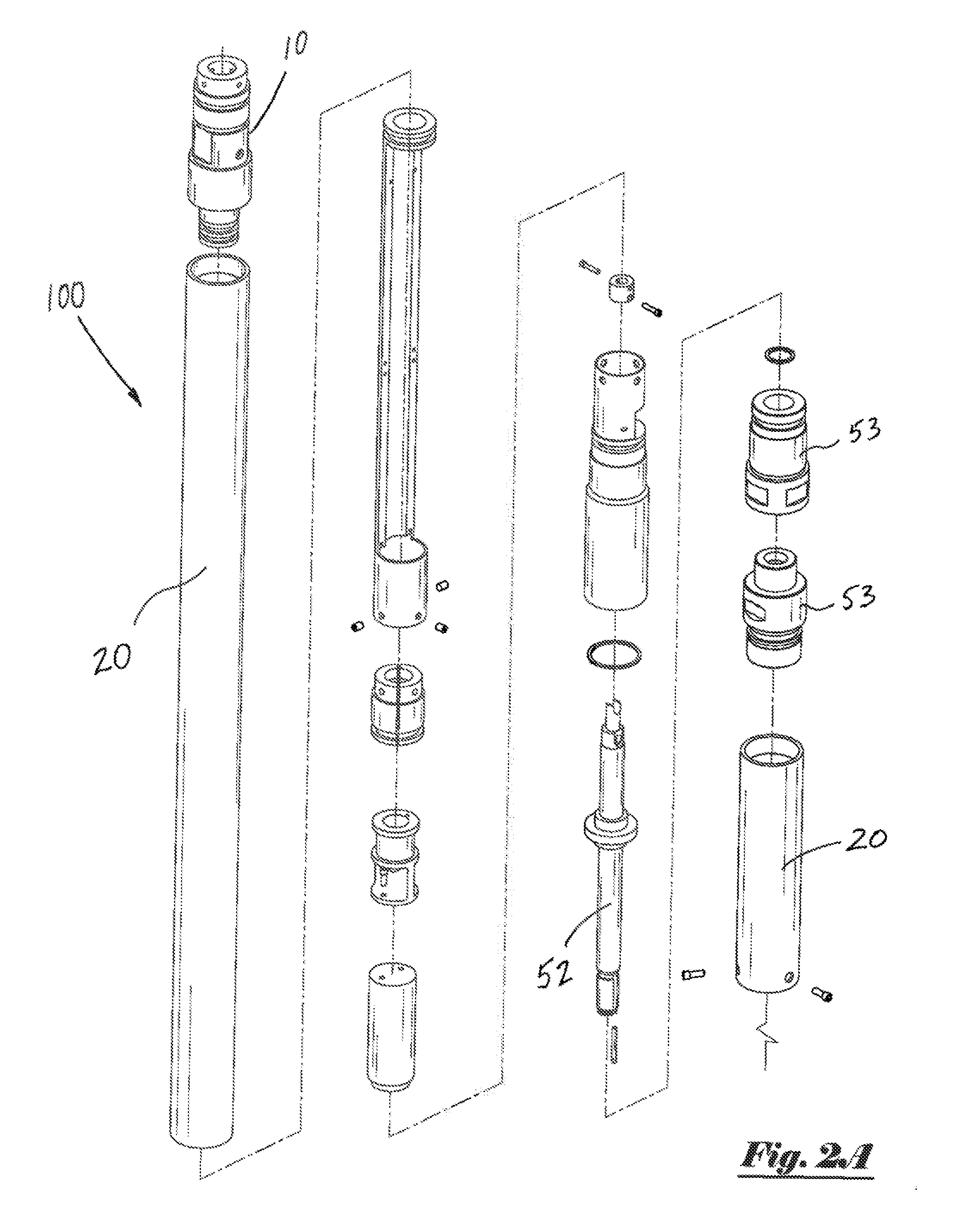
[0020]The application on which this application claims priority under 35 USC 119(e), U.S. Provisional Patent Application No. 61 / 906,457, filed Nov. 20, 2013, is hereby incorporated herein by reference. The present invention comprises a method and apparatus for beneficially illuminating a portion of a downhole wellbore environment. Live video data or other visual images can be acquired within said wellbore, and recorded to onboard data storage and / or transmitted to the earth's surface for viewing, evaluation and / or other purposes. In addition to downward views (that is, views that are substantially aligned with the longitudinal axis of a wellbore and oriented generally toward the distal end of said wellbore), the present invention permits viewing of subject matter that is positioned laterally to said apparatus—that is, subject matter that is positioned substantially perpendicular to the longitudinal axis of said wellbore.

[0021]FIG. 1 depicts a side perspective view of a downhole side...


PUM


Abstract

A downhole camera assembly (100) comprises a camera having a side-view viewport (82) that can be conveyed and manipulated within a wellbore on flexible cable. Light emitted from a light source is diffused and directed by a transparent or translucent material (61) in a substantially 360-degree pattern within a wellbore, thereby illuminating portion(s) of the wellbore positioned laterally to the camera assembly in a field of view of the viewport. The viewport may be selectively rotated 360 degrees by a motor assembly (40) positioned within the camera assembly which can be controlled from the earth's surface.

Description

TECHNICAL FIELD[0001]The present invention pertains to a camera and associated lighting system for use in unlighted and / or harsh environments. More particularly, the present invention pertains to a downhole illuminated camera systems for use in wells penetrating subterranean formations including, without limitation, oil and / or gas wells.BACKGROUND ART[0002]Downhole camera systems exist for obtaining video and / or still visual images in wellbores. However, most wellbores contain little or no existing source of ambient or available light. Accordingly, a light source must typically be provided in order to illuminate downhole portions of a wellbore when use of a camera or other visual image sensor in such areas is desired.[0003]Certain conventional downhole camera systems utilize lamp(s) or other light sources to illuminate downhole portions of a wellbore for viewing. In one example, an incandescent light bulb is placed behind a camera body having a reflector. In another example, a low v...

Claims


Application Information

Patent Timeline
Patent Type & Authority Applications(United States)
IPC IPC(8): G03B37/00H04N7/18E21B47/00
CPCG03B37/005H04N7/185E21B47/0002E21B47/002E21B47/017G02B23/24
Inventor HARRIS, MARSHALSCHULTZ, PHILIPMEYERS, CHRISTOPHERBEACOM, BRUCE
Owner ABRADO
Why Eureka
Try Eureka