
Method And Apparatus For Wi-Fi Access Optimization

Inactive Publication Date: 2016-09-08
ALCATEL-LUCENT USA INC
View PDF3 Cites 9 Cited by
  • Summary
  • Abstract
  • Description
  • Claims
  • Application Information

AI Technical Summary

Benefits of technology

This patent is about improving the efficiency of wireless systems that use Wi-Fi technologies. This is especially important for small cells, which are low-cost, low-power devices that help improve coverage and capacity of wireless networks. These small cells need to be close to each other to provide consistent service and high capacity, and they can support multiple technologies at the same time. Many LTE small cell products already have carrier Wi-Fi enabled.

Problems solved by technology

Wi-Fi networks are very challenged in open, high density traffic areas, and in general, in environments requiring high capacity, where a large number of Access Points (APs) need to be deployed in close proximity to each other for capacity reasons.
Moreover, the high level of resulting interference pollution is further amplified when some users decide independently to configure their Wi-Fi enabled devices as temporary APs.
This is because the 802.11 Medium Access Control (MAC) with Carrier Sensing Multiple Access and Collision Avoidance (CSMA / CA) is a distributed access mechanism that is known not to perform well in highly congested areas, which are areas in which the medium is almost continuously busy.
While RF planning and channel assignment is a very critical optimization procedure, it has limitations that are easy to understand in open public spaces, such as stadiums during sporting events.
Even with a large number of independent non-overlapping channels (e.g., as permitted in the 5 GHz spectrum), the high capacity requirements call for a very tight Wi-Fi AP-to-AP spatial separation, which combined with reflection and bouncing of radio signals may result in significant co-channel interference.
The combination of heavy traffic (high activity) and radio pollution drive the Wi-Fi operation towards a less efficient regime (e.g., lower achievable rates and poor overall system performance).

Method used


Image

  • Method And Apparatus For Wi-Fi Access Optimization
  • Method And Apparatus For Wi-Fi Access Optimization
  • Method And Apparatus For Wi-Fi Access Optimization

Examples


Embodiment Construction

[0025]Various example embodiments will now be described more fully with reference to the accompanying drawings in which some example embodiments are shown.

[0026]Detailed illustrative embodiments are disclosed herein. However, specific structural and functional details disclosed herein are merely representative for purposes of describing example embodiments. The principles of the invention may, however, be embodied in many alternate forms and should not be construed as limited to only the embodiments set forth herein.

[0027]Accordingly, while example embodiments are capable of various modifications and alternative forms, the embodiments are shown by way of example in the drawings and will be described herein in detail. It should be understood, however, that there is no intent to limit example embodiments to the particular forms disclosed. On the contrary, example embodiments are to cover all modifications, equivalents, and alternatives falling within the scope of this disclosure. Like...


PUM


Abstract

A method for controlling a plurality of Wi-Fi clients and a plurality of Wi-Fi Access Points (APs) is provided. The method receives M1 and M2 for the Wi-Fi clients and M3 for the Wi-Fi APs. For a respective Wi-Fi client configured to operate on a channel, M1 is a Received Signal Strength Indication (RSSI) from a serving Wi-Fi AP and M2 is an aggregated level of interference from other than the serving Wi-Fi AP. For a respective Wi-Fi AP, M3 is a level of interference received from other of the Wi-Fi APs operating on the channel. The method generates distributions of M1, M2 and M3, sets a Clear Channel Assessment-Energy Detection (CCA-ED) threshold and a Clear Channel Assessment-Carrier Sense (CCA-CS) threshold based on the distributions of M1, M2 and M3, and transmits the thresholds to the Wi-Fi clients and Wi-Fi APs.

Description

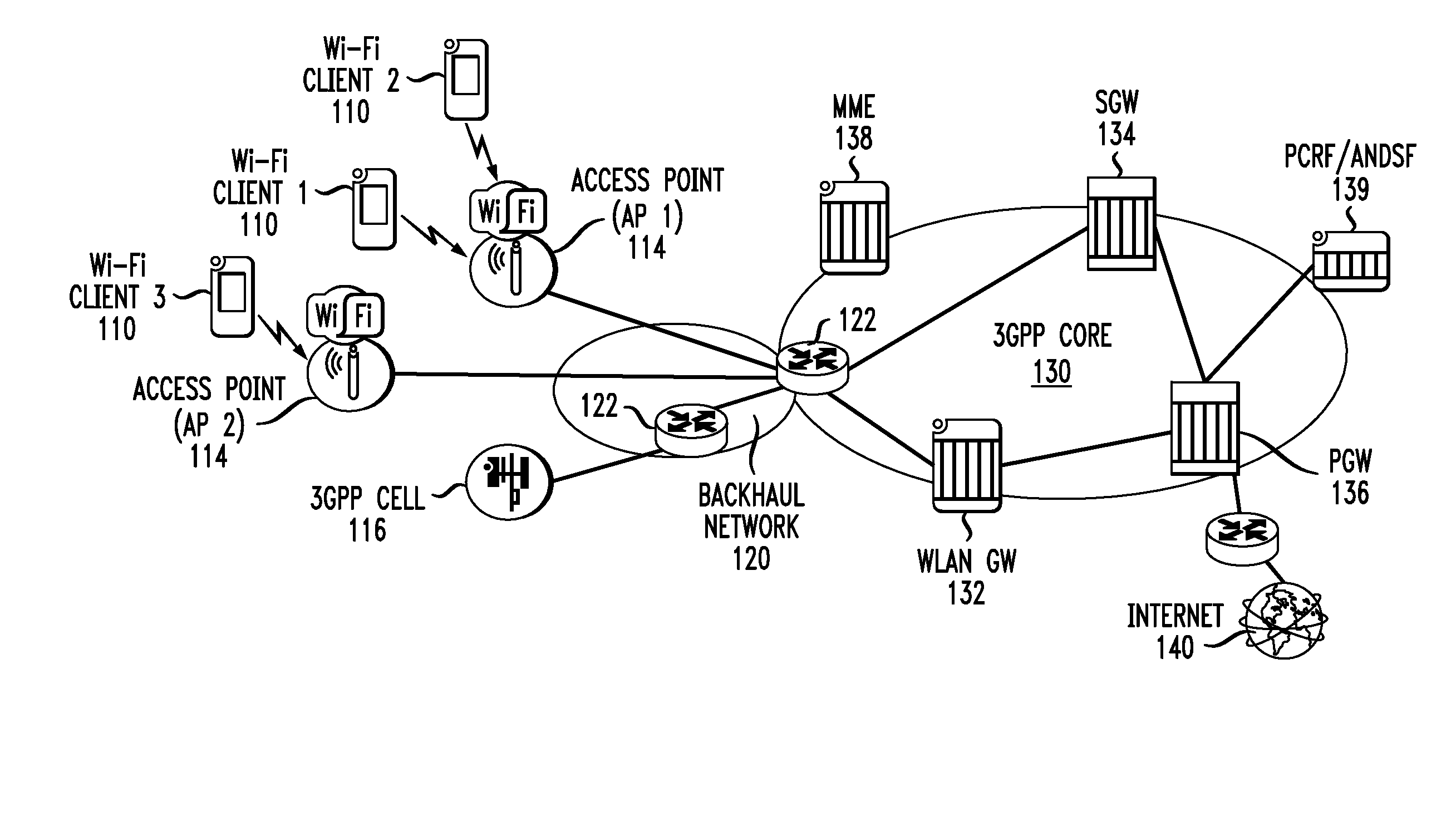
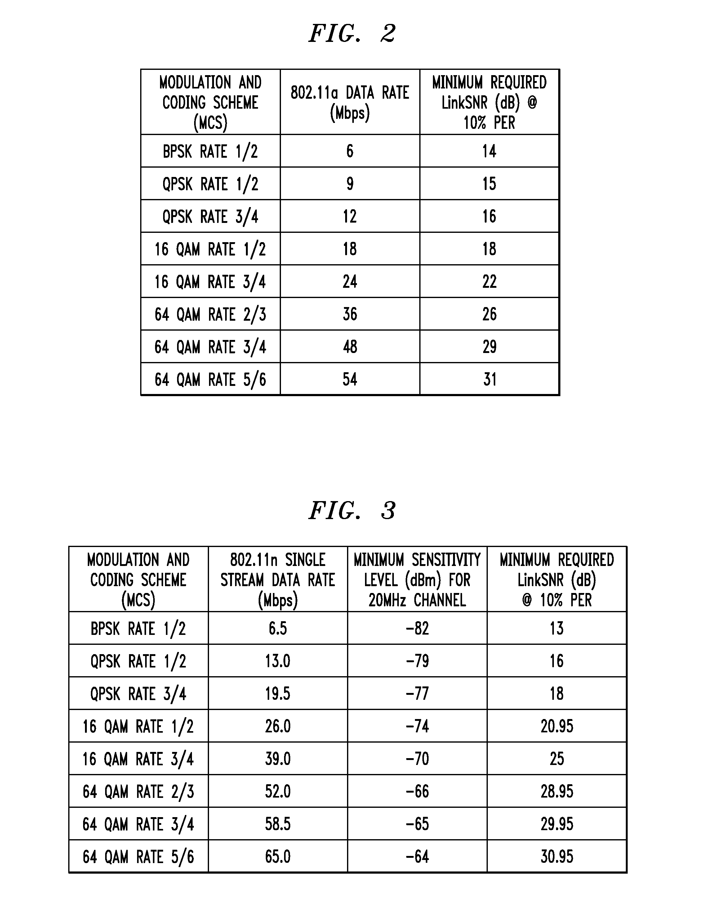
BACKGROUND[0001]1. Field[0002]This application relates generally to communication systems, and, more particularly, to Wi-Fi communication systems.[0003]2. Related Art[0004]Wi-Fi networks are very challenged in open, high density traffic areas, and in general, in environments requiring high capacity, where a large number of Access Points (APs) need to be deployed in close proximity to each other for capacity reasons. Moreover, the high level of resulting interference pollution is further amplified when some users decide independently to configure their Wi-Fi enabled devices as temporary APs.[0005]This is because the 802.11 Medium Access Control (MAC) with Carrier Sensing Multiple Access and Collision Avoidance (CSMA / CA) is a distributed access mechanism that is known not to perform well in highly congested areas, which are areas in which the medium is almost continuously busy. Highly congested areas are typical to public venues (e.g., airports, concert arenas, stadium environments du...

Claims


Application Information

Patent Timeline
IPC IPC(8): H04W72/08H04L5/00
CPCH04W72/082H04W88/08H04W84/12H04L5/0048H04W24/02H04W74/002
Inventor CALIN, DORUKAYA, ALIYE OZGE
Owner ALCATEL-LUCENT USA INC
Learn More