
LED driver, lighting equipment and light fixture

Inactive Publication Date: 2016-09-08
PANASONIC INTELLECTUAL PROPERTY MANAGEMENT CO LTD
View PDF0 Cites 7 Cited by
  • Summary
  • Abstract
  • Description
  • Claims
  • Application Information

AI Technical Summary

Benefits of technology

The technical effect of this patent text is to increase the range of adjustment for the drive current of an LED light source while reducing the loss of lighting equipment and fixtures.

Problems solved by technology

With the DC dimming method, there is a limit (a lower limit) in an ON period (an ON width) of a drive signal supplied from a drive circuit for driving the switching device to a control terminal (a gate terminal) of the switching device, thereby making it difficult to perform deep dimming.
In comparison with a switching regulator, the dropper regulator has an advantage of low ripple and low noise, but has disadvantages of low conversion efficiency and the like.
However, in the case of the linear dimming method, loss increases according to an increase in a difference between input and output voltages of the LED driver, thereby decreasing the conversion efficiency.

Method used


Image

  • LED driver, lighting equipment and light fixture
  • LED driver, lighting equipment and light fixture
  • LED driver, lighting equipment and light fixture

Examples


Embodiment Construction

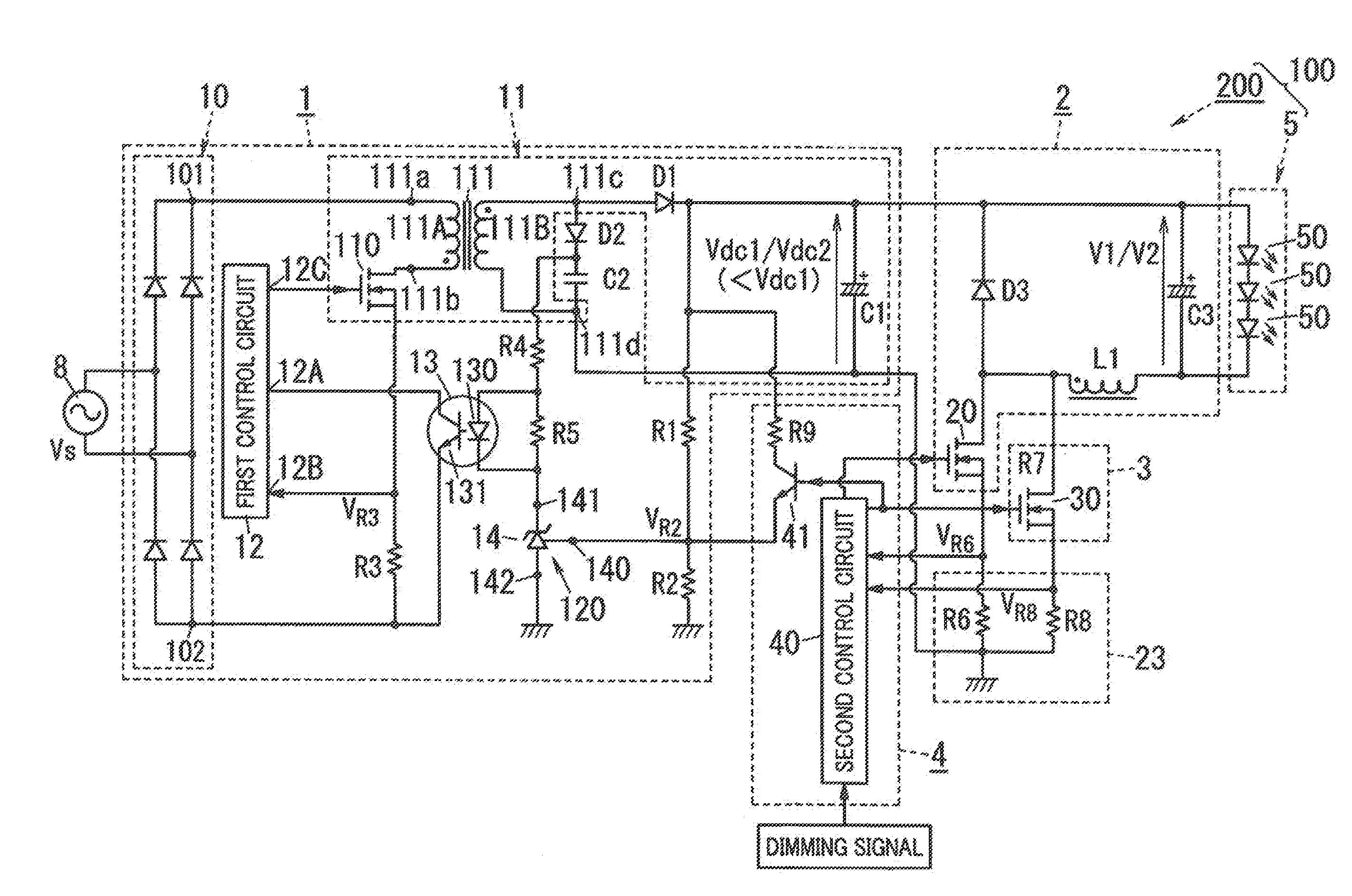
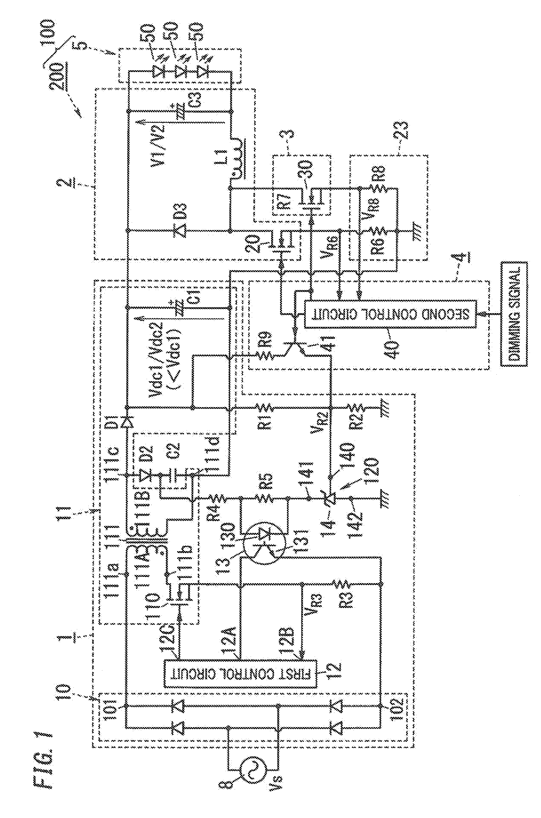
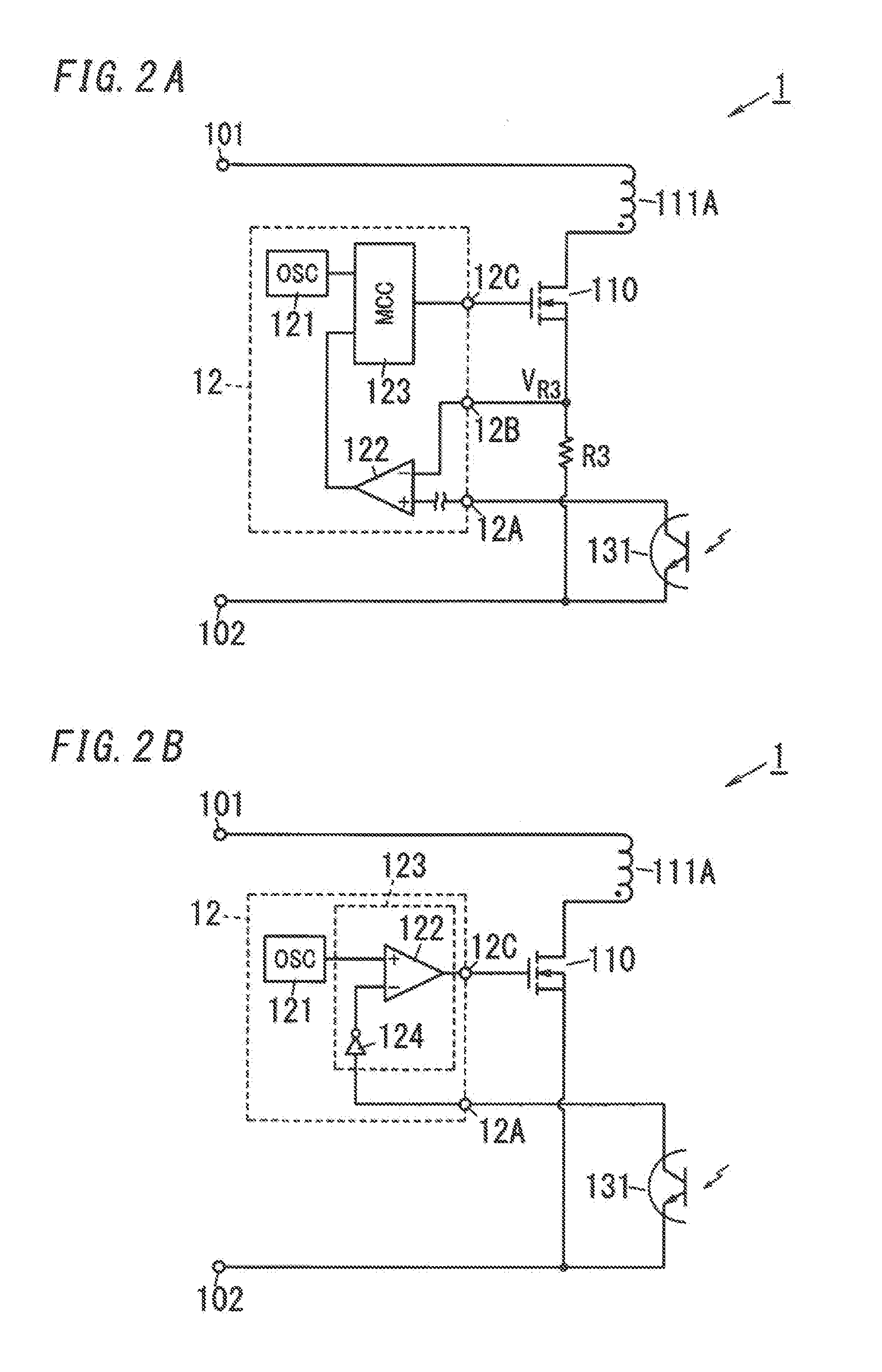
[0019]An LED (Light-Emitting Diode) driver and lighting equipment, in accordance with an embodiment will be explained with reference to FIGS. 1 to 4.

[0020]The LED driver 200 according to the embodiment is configured to light an LED light source 5. In an example of FIG. 1, the LED driver 200 includes a DC (Direct Current) power supply 1, a switching regulator 2, a dropper regulator 3 and a controller 4.

[0021]As shown in FIG. 1, the lighting equipment 100 according to the embodiment includes the LED driver 200 and the LED light source 5. The LED light source 5 is formed of a series circuit of a plurality of (three in the example of FIG. 1) LEDs 50. The number of LEDs 50 constituting the LED light source 5 is not limited to three, but may be two or less or four or more. The LED light source 5 may be also formed of a parallel circuit of LED arrays each of which includes a plurality of (e.g., twenty) LEDs in series. The LED light source 5 is electrically connected between output terminal...


PUM


Abstract

When supplying an LED light source with a first output voltage that is equal to or higher than a threshold voltage, an LED driver causes a DC power supply to output a first DC voltage and causes a switching regulator to supply the LED light source with the first output voltage. When supplying the LED light source with a second output voltage that is below the threshold voltage, the LED driver causes the DC power supply to output a second DC voltage lower than the first DC voltage and causes the dropper regulator to supply the LED light source with the second output voltage.

Description

CROSS REFERENCE TO RELATED APPLICATIONS[0001]This application claims the benefit and priority of Japanese Patent Application No. 2015-041688, filed on Mar. 3, 2015, the entire contents of which are incorporated herein by reference.TECHNICAL FIELD[0002]The disclosure relates generally to LED drivers, lighting equipment and light fixtures and, more particularly, to an LED (Light-Emitting Diode) driver configured to drive (light) an LED light source, lighting equipment including an LED light source as an illumination light source and the LED driver, and a light fixture having the lighting equipment.BACKGROUND ART[0003]A solid light source lighting device as a prior art is exemplified in JP Pub. No. 2012-221899 (hereinafter referred to as “Document 1”). The solid light source lighting device described in Document 1 includes a buck chopper circuit, and is configured to dim, namely adjust a light output of a solid light source (e.g., an LED (Light-Emitting Diode) light source) by controll...

Claims


Application Information

Patent Timeline
IPC IPC(8): H05B33/08H05B44/00
CPCH05B33/0845H05B33/0815H05B45/10Y02B20/30H05B45/3725H05B45/385H05B47/10
Inventor KANGYO, MIYOWATANABE, KOJIKUMADA, KAZUHIROMURAKAMI, SHINICHI
Owner PANASONIC INTELLECTUAL PROPERTY MANAGEMENT CO LTD
Learn More