
Vehicle control device

a technology of vehicle control and control device, which is applied in the direction of hybrid vehicles, electrical control, ignition automatic control, etc., can solve the problems of increasing the number of starters, the number of times, and the increase of the starting devi

Inactive Publication Date: 2016-09-15
TOYOTA JIDOSHA KK
View PDF0 Cites 9 Cited by
  • Summary
  • Abstract
  • Description
  • Claims
  • Application Information

AI Technical Summary

Benefits of technology

The patent text explains a method for restarting an engine without using a starting device. This method involves increasing the speed of the engine by transmitting torque from the drive wheel to the crankshaft. However, this method results in decelerating acceleration on the vehicle, which can make the driver uncomfortable and negatively affect driving performance. The technical effect of this patent is to provide an improved method for restarting an engine without the need for a starting device that minimizes decelerating acceleration and provides better driving comfort.

Problems solved by technology

However, when the engine is frequently stopped and restarted during travel, the number of times to restart the engine by driving the starting device such as the starter motor increases and usage frequency of the starting device increases.
When the usage frequency of the starting device increases, a load on the starting device increases and a lifetime of the starting device might be short.
However, in the restarting method using the push starting, decelerating acceleration (deceleration G) occurs on the vehicle, so that a driver might feel uncomfortable, and drivability might be deteriorated.

Method used


Image

  • Vehicle control device
  • Vehicle control device
  • Vehicle control device

Examples


Embodiment Construction

[0014]One embodiment of the present disclosure is hereinafter described with reference to the drawings. Meanwhile, the same reference sign is assigned to the same or corresponding parts in all the drawings of one embodiment below. The present disclosure is not limited by one embodiment described below.

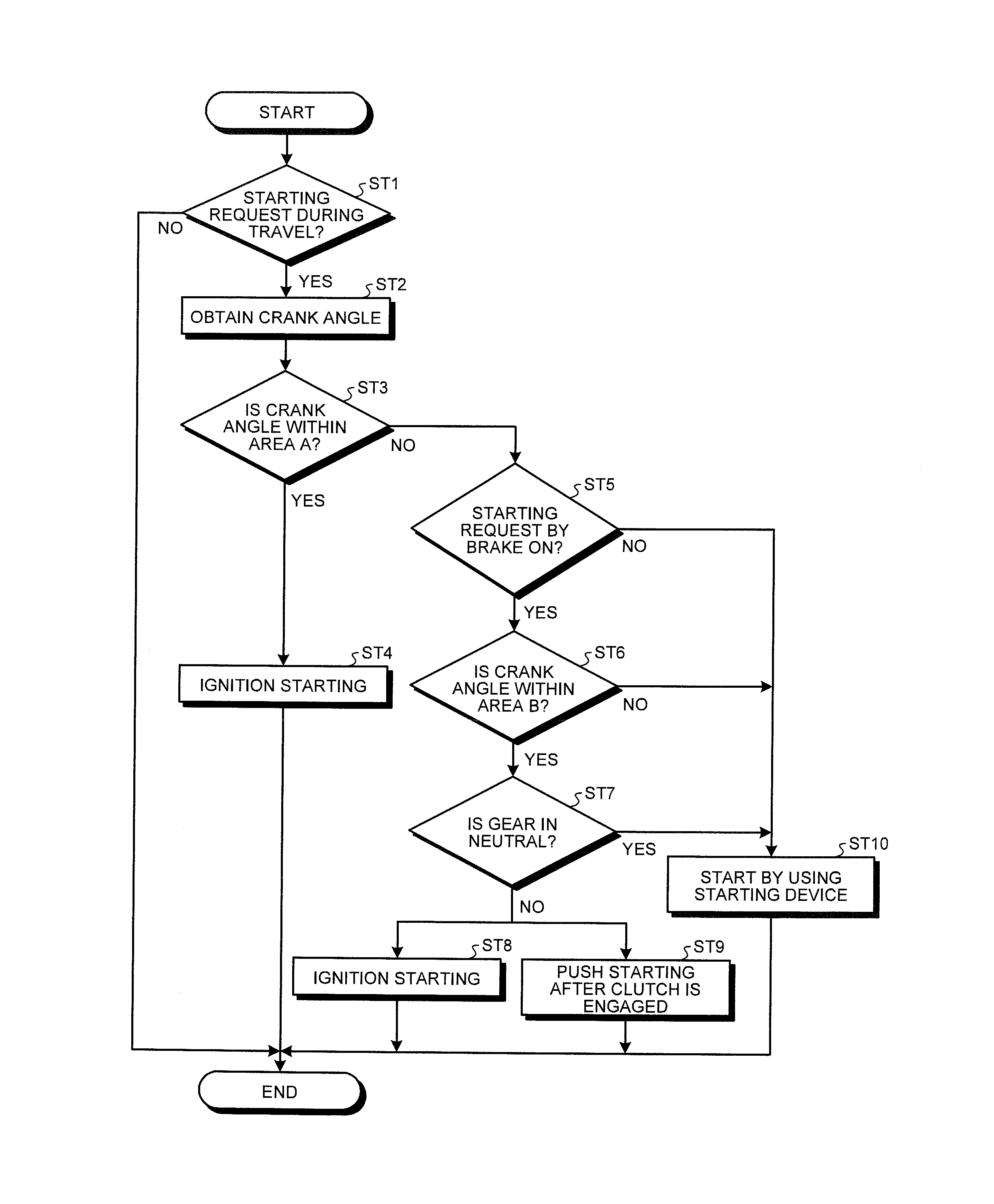
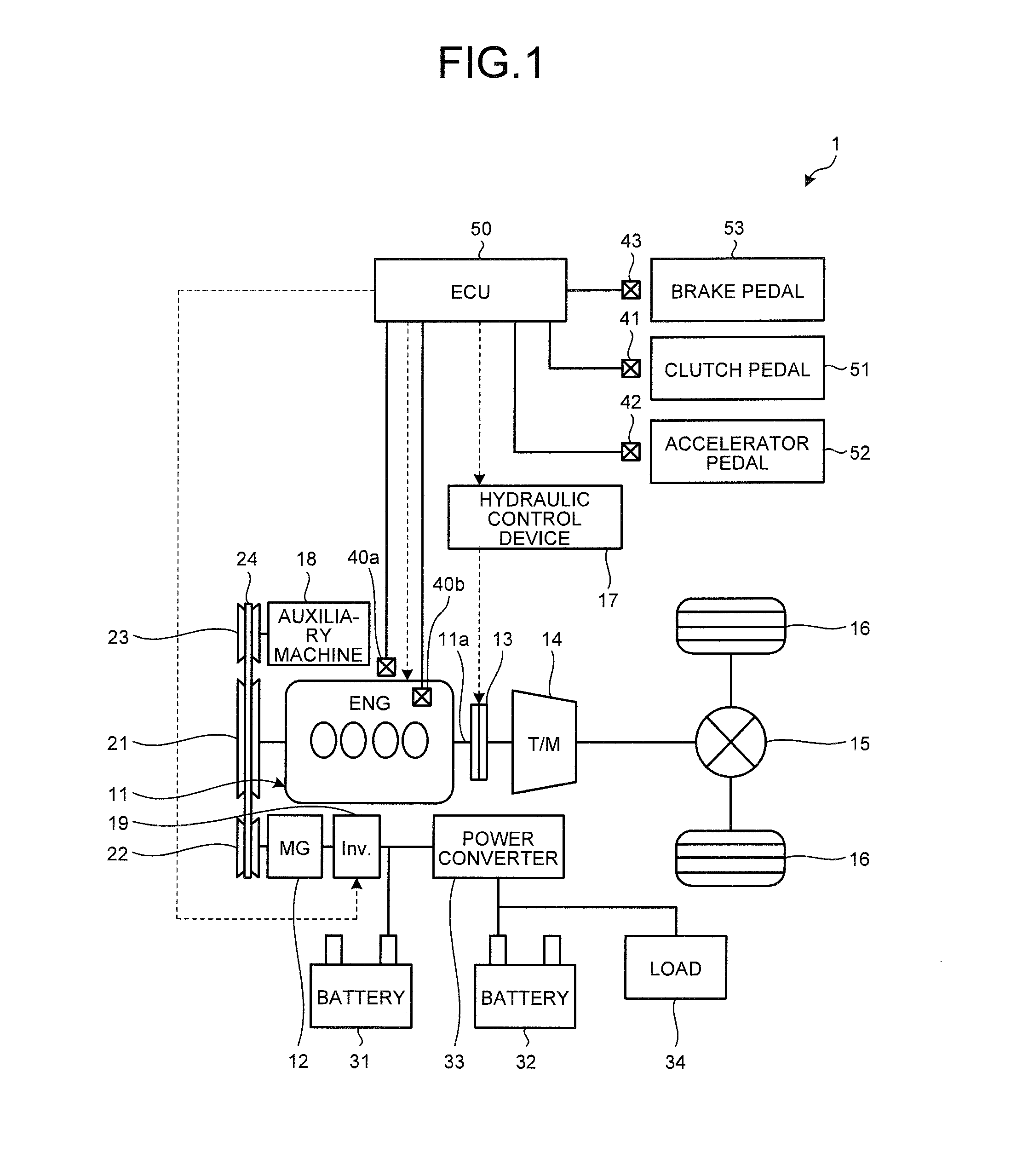
[0015]FIG. 1 is a schematic configuration diagram illustrating a vehicle on which a vehicle control device according to one embodiment is mounted. A vehicle 1 illustrated in FIG. 1 is a one motor-type hybrid vehicle, for example. The vehicle 1 includes an engine (ENG) 11, a motor / generator (MG) 12, a clutch 13, a stepped transmission (T / M) 14, a differential gear 15, and right and left drive wheels 16. The vehicle 1 includes a hydraulic control device 17, an auxiliary machine 18, an inverter 19, pulleys 21, 22, and 23, a transmission belt 24 stretched around the pulleys 21, 22, and 23, a high-voltage battery 31, a battery 32, a power converter 33, and a load 34. The vehicle 1 is furthe...


PUM


Abstract

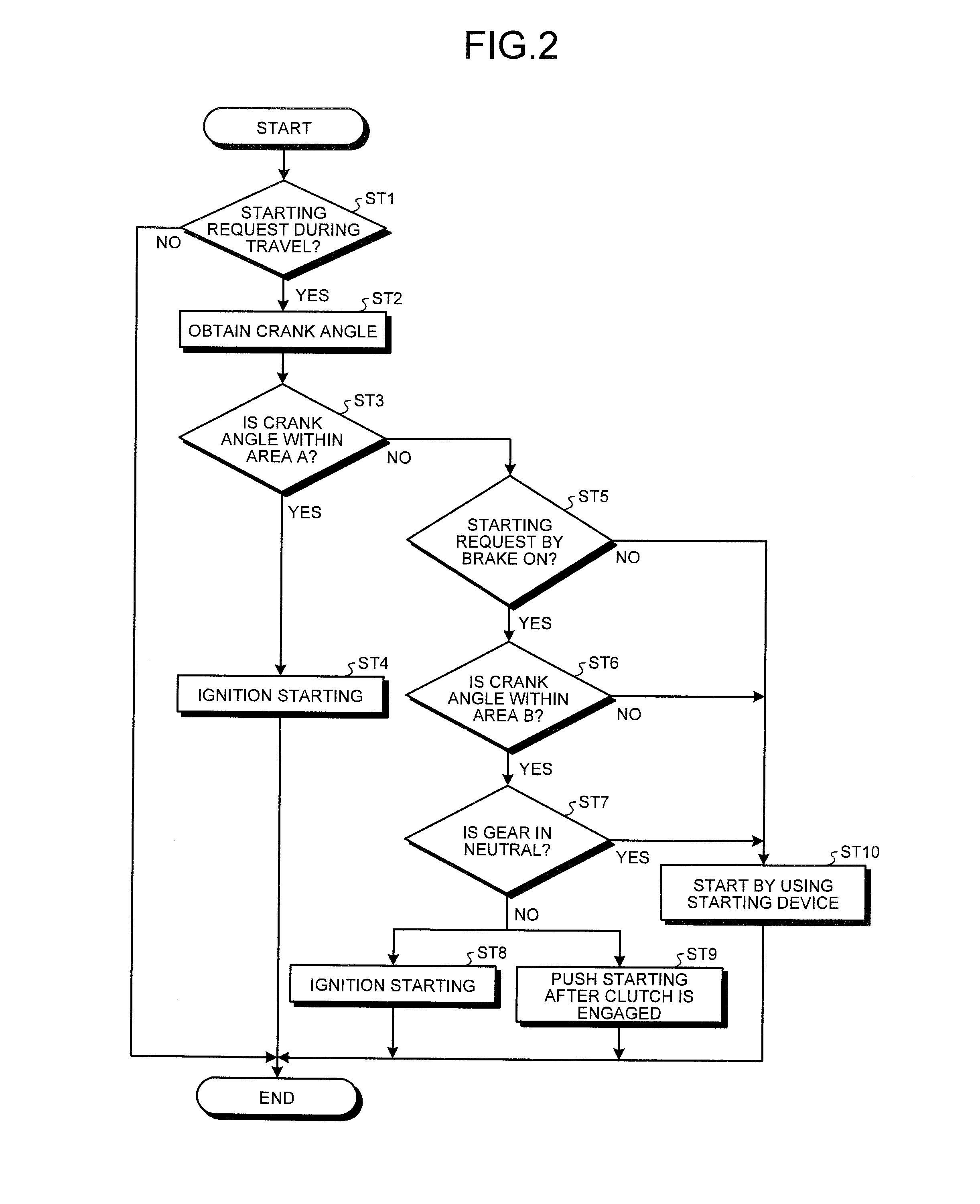
A vehicle control device includes a controller configured to perform: ignition starting of an engine when a detected crank angle is within a first area in which the ignition starting of the engine may be performed with probability not smaller than a first predetermined value; and the ignition starting of the engine while increasing an engine speed by engaging a clutch to transmit torque of a drive wheel to a crankshaft when the crank angle is within a second area in which the ignition starting of the engine may be performed with probability not smaller than a second predetermined value smaller than the first predetermined value and smaller than the first predetermined value, the instruction is output based on a signal indicating that a braking unit is turned on, and a gear of a transmission is not in neutral.

Description

CROSS-REFERENCE TO RELATED APPLICATION(S)[0001]The present application claims priority to and incorporates by reference the entire contents of Japanese Patent Application No. 2015-049888 filed in Japan on Mar. 12, 2015.BACKGROUND OF THE DISCLOSURE[0002]1. Field of the Disclosure[0003]The present disclosure relates to a vehicle control device.[0004]2. Description of the Related Art[0005]Various methods of restarting an engine when restarting the engine stopped while a vehicle is driven are conventionally suggested. For example, Japanese Patent Application Laid-open No. 2005-16356 discloses the technology to restart by ignition starting of the engine when a stopping position of a piston of the engine is within a predetermined appropriate range and to assist the restart of the engine by driving a starter motor when this is outside the predetermined appropriate range.[0006]However, when the engine is frequently stopped and restarted during travel, the number of times to restart the engi...

Claims


Application Information

Patent Timeline
Patent Type & Authority Applications(United States)
IPC IPC(8): B60W30/18B60W10/06F02N11/08B60W10/02F02D41/02F02D41/06
CPCB60W30/18F02D41/022F02D41/065F02N11/08B60W10/02B60W2710/0644B60W2510/0685B60W2510/1005B60W2510/18B60W2710/021B60W10/06B60W30/18018F02D37/02F02D41/062F02D41/30F02P5/045B60W10/08B60W20/40B60W30/18072B60W2030/1809B60W2510/101B60W2540/12F02N11/0803F02N11/0822F02N19/005F02N99/002F02N2200/0802F02N2200/102Y02T10/40Y02T10/62
Inventor MATSUSHITA, KOKI
Owner TOYOTA JIDOSHA KK
Learn More