Eureka AIR delivers breakthrough ideas for toughest innovation challenges, trusted by R&D personnel around the world.

Charging member

a charging member and charging roller technology, applied in the field of charging members, can solve the problems of increasing the cost of the device itself, affecting the charging ability of the charging roller, and the durability of the charging roller or the photoconductor may deteriorate, so as to improve the charging ability, the electrostatic capacity may increase, and the charging properties are stable.

Active Publication Date: 2016-09-15
HEWLETT PACKARD DEV CO LP
View PDF6 Cites 12 Cited by
  • Summary
  • Abstract
  • Description
  • Claims
  • Application Information

AI Technical Summary

Benefits of technology

The present patent provides a charging member that can maintain stable charging properties even when only a direct current voltage is applied. The charging member can produce excellent images without image roughness, initial image defects, and image defects caused by particles dropped-out during a durability test. The conductive resin layer formed as a thin film increases electrostatic capacity and improves charging ability. An uneven surface may be formed on the conductive resin layer to secure discharge points and prevent particle drop-out, thus improving the durability of the charging member.

Problems solved by technology

However, since it is needed to use a high AC voltage having a peak-to-peak voltage that is twice or greater a discharge start voltage (Vth) of a DC voltage to be applied, a separate AC power supply, in addition to a DC power supply, is needed, which results in an increase in a cost of the device itself.
Also, a large amount of close proximity discharging may occur between the charging member (e.g., a charging roller) and a photoconductor, and thus the durability of the charging roller or the photoconductor may deteriorate.
In particular, the photoconductor may be easily abrased.

Method used


Image

  • Charging member
  • Charging member
  • Charging member

Examples


example 1

Preparation of Material for Forming Conductive Elastomer Layer

[0066]100.00 parts by weight of epichlorohydrin rubber (“Epichlomer CG-102”, available from Daiso, Japan), as a rubber component; 5.00 parts by weight of sorbitan fatty acid ester (“Splendor R-300”, available from Kao Chemicals, Japan), as a lubricant; 5.00 parts by weight of ricinoleic acid, as a softener; 0.50 parts by weight of a hydrotalcite-based compound (“DHT-4A”, available from Kyowa Chemical Industry, Japan), as a neutralizing agent; 1.00 part by weight of tetrabuyl ammonium chloride (an ion conducting agent, “tetrabuyl ammonium chloride”, available from Tokyo Chemical, Japan); 50.00 parts by weight of silica (“Nipsil ER”, available from Tosoh Silica Co. Japan), as a filler; 5.00 parts by weight of zinc oxide, 1.50 parts by weight of dibenzothiazolyl disulfide, and 0.50 parts by weight of tetramethylsilane monosulfide, as a cross-linking accelerator; and 1.05 parts by weight of sulfur, as a cross-linking agent we...


PUM


Abstract

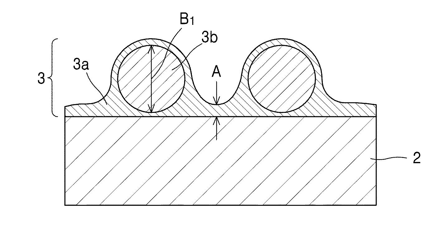
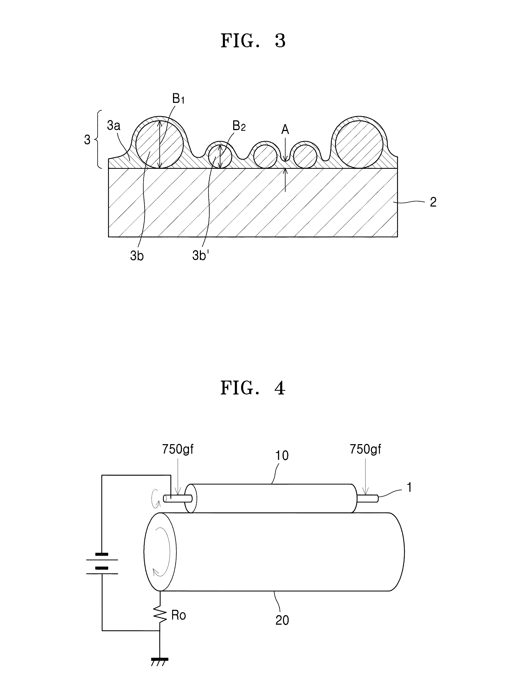
A charging member, one embodiment of which includes a conductive support; a conductive elastomer layer stacked on the conductive support; and a conductive resin layer stacked on the conductive elastomer layer, wherein the conductive resin layer includes: a matrix material; and a plurality of particles dispersed in the matrix material, wherein the particles include first particles, and when a thickness of a portion formed of the matrix material alone of the conductive resin layer is referred to as A [μm], an average particle size of the first particles is referred to as B1 [μm], and an interparticle distance of the particles is referred to as Sm [μm], then A is in a range of 1.0 μm to 7.0 μm, B1 / A is in a range of 5.0 to 30.0, and Sm is in a range of 50 μm to 400 μm.

Description

TECHNICAL FIELD[0001]The inventive concept relates to a charging member, and more particularly, to a charging member that charges an image carrier (e.g., a photoconductor) that is used in an electrostatic latent image process applied to an electrophotographic image forming device.BACKGROUND ART[0002]Conventionally, “an alternating current (AC) charging technique” that applies a voltage of a direct current (DC) voltage component overlapped with an AC voltage component to a contact charging member has been used in order to improve charging evenness. However, since it is needed to use a high AC voltage having a peak-to-peak voltage that is twice or greater a discharge start voltage (Vth) of a DC voltage to be applied, a separate AC power supply, in addition to a DC power supply, is needed, which results in an increase in a cost of the device itself. Also, a large amount of close proximity discharging may occur between the charging member (e.g., a charging roller) and a photoconductor, ...

Claims


Application Information

Patent Timeline
IPC IPC(8): G03G15/02
CPCG03G15/0233
Inventor KURODA, NORIAKI
Owner HEWLETT PACKARD DEV CO LP
Why Eureka
Eureka Blog
Learn More