Front end circuit and wireless communication device

a front-end circuit and wireless communication technology, applied in the field of front-end circuits and wireless communication devices, can solve the problems of difficult to widen the range over which the impedance can be adjusted, the control system is not easy to work, and the circuit scale of the antenna circuit is complicated, so as to achieve the effect of increasing isolation

Active Publication Date: 2016-09-15
MURATA MFG CO LTD
View PDF5 Cites 3 Cited by
  • Summary
  • Abstract
  • Description
  • Claims
  • Application Information

AI Technical Summary

Benefits of technology

[0019]The front end circuit according to this disclosure can further include a transmission filter connected to the transmission port and a reception filter connected to the reception port. In addition, each of the transmission filter and the reception filter can be constituted of, for example, a tunable filter having a variable reactance element or a selectable filter having a switch and a plurality of filt

Problems solved by technology

However, widening the range over which the impedance can be adjusted in an antenna tuner requires increasing the number of control elements such as variable capacitors, which complicates the circuit scale of the antenna circuit, the control system, and so on.
However, it is difficult to widen the range over which the impedance can be adjusted to levels currently in demand while maintaining a realistic scale for t

Method used


Image

  • Front end circuit and wireless communication device
  • Front end circuit and wireless communication device
  • Front end circuit and wireless communication device

Examples


first embodiment

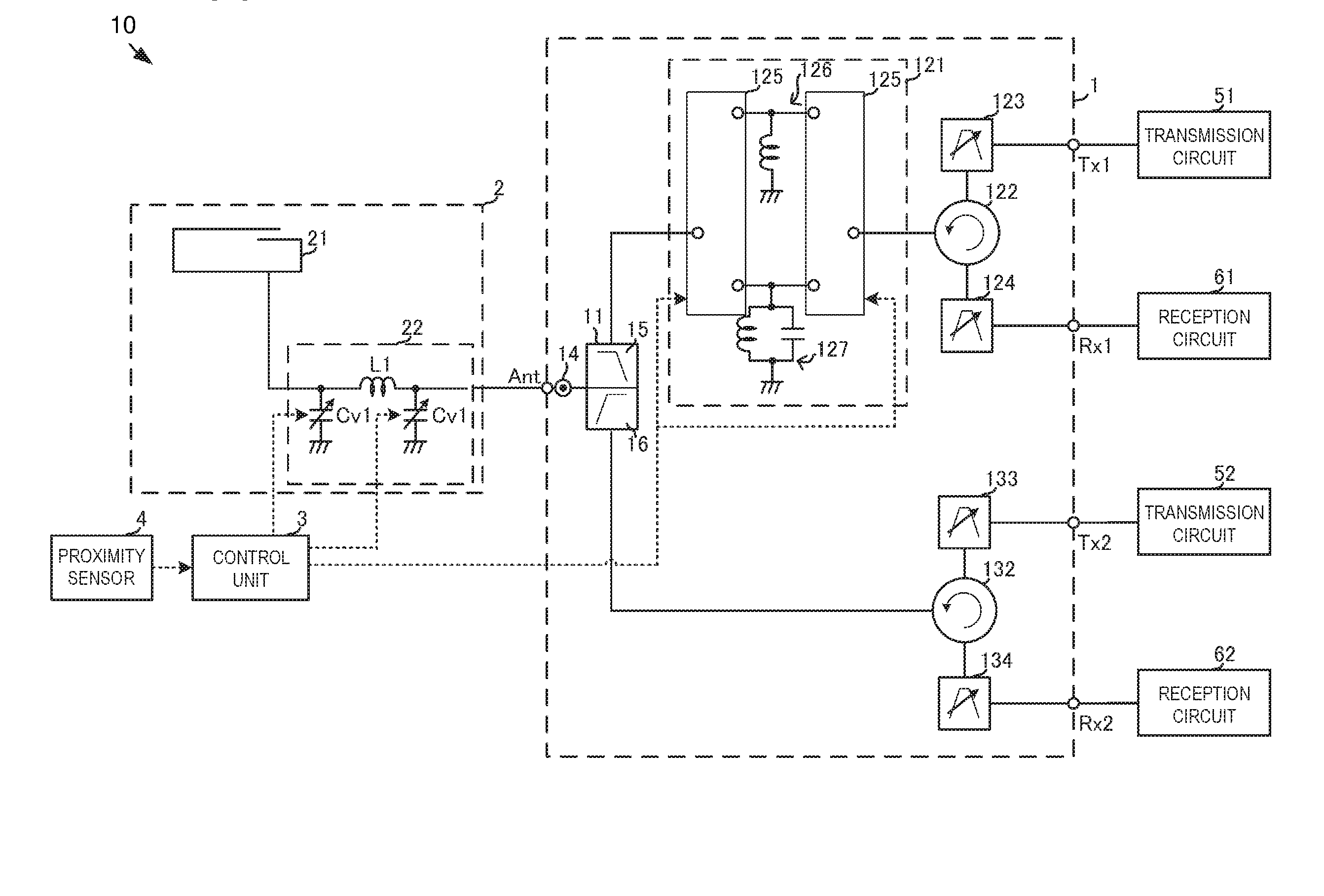
[0037]FIG. 3 is a circuit block diagram illustrating a front end circuit and a wireless communication device according to the present embodiment. A wireless communication device 10 according to the present embodiment transmits and receives using multiple communication bands on a low-frequency band side and multiple communication bands on a high-frequency band side. In the case of LTE, for example, a low-frequency band-side communication band is a communication band of approximately 1 GHz or lower. In the case of LTE, for example, a high-frequency band-side communication band is a communication band of approximately 1.4 GHz or higher.

[0038]The wireless communication device 10 includes a front end circuit 1, an antenna circuit 2, a control unit 3, a proximity sensor 4, transmission circuits 51 and 52, and reception circuits 61 and 62.

[0039]The front end circuit 1 transmits and receives in each communication band through the antenna circuit 2. As such, the front end circuit 1 has a tra...

second embodiment

[0070]A wireless communication device 10A and a front end circuit 1A according to a second embodiment of the present disclosure will be described next. FIG. 4 is a circuit block diagram illustrating the wireless communication device 10A and the front end circuit 1A according to the present embodiment. The wireless communication device 10A and the front end circuit 1A include matching circuits 126A and 127A instead of the matching circuits 126 and 127 described in the first embodiment. The matching circuits 126A and 127A are variable impedance circuits having variable reactance elements such as digital tuning capacitors (DTC).

[0071]When the current state is determined to be the antenna non-proximate state, the control unit 3 controls the variable matching circuit 121 to cause the high-frequency switch 125 to connect the matching circuit 126A to the signal path. Meanwhile, when the current state is determined to be the antenna proximate state, the control unit 3 controls the variable ...

third embodiment

[0075]A wireless communication device 10B and a front end circuit 1B according to a third embodiment of the present disclosure will be described next. FIG. 5 is a circuit block diagram illustrating the wireless communication device 10B and the front end circuit 1B according to the present embodiment. The wireless communication device 10B and the front end circuit 1B have switchplexers 122B and 132B and pluralities of duplexers 123B and 133B, instead of the circulators 122 and 132 as well as the transmission filters 123 and 133 and the reception filters 124 and 134 according to the first embodiment. The plurality of duplexers 123B handles respective low-frequency communication bands, and is constituted by a transmission filter and a reception filter that take those communication bands as their pass bands. The plurality of duplexers 133B handles respective high-frequency communication bands, and is constituted by a transmission filter and a reception filter that take those communicati...


PUM


Abstract

A front end circuit includes a variable matching circuit connected to a diplexer and a switch connector connected between an antenna port and the diplexer. The variable matching circuit selectively connects matching circuits to a signal path. When one of the matching circuits is connected, the impedance as viewed from the switch connector matches an impedance of a measurement circuit near a normalized impedance of 1 in a predetermined communication band, whereas when the other matching circuit is connected, the impedance viewed from the antenna port conjugate-matches the impedance of an antenna circuit in a predetermined communication band.

Description

BACKGROUNDTechnical Field[0001]The present disclosure relates to a front end circuit and a wireless communication device in which an antenna is shared for signal transmission and signal reception in predetermined communication bands.[0002]At present, wireless communication devices such as cellular phone terminals are configured to use multiple types of communication bands. A front end circuit is used in a wireless communication device in order to handle such a variety of communication bands using a single or a small number of antenna circuits. A front end circuit is typically provided with, for example, a shared antenna device that uses a circulator, a duplexer, a switchplexer, or the like, filters corresponding to the respective transmission signals and reception signals, and a switch connector for measuring the transmission output, reception sensitivity, and so on at an antenna port. The switch connector is an element to which a measurement circuit for measuring the transmission o...

Claims


Application Information

Patent Timeline
IPC IPC(8): H01Q1/50
CPCH01Q1/50H03H7/40H03H7/463H04B1/0458H04B1/18
Inventor ONAKA, KENGOTANAKA, HIROYAOBIYA, HIDENORI
Owner MURATA MFG CO LTD
Why Eureka
Try Eureka