
Floating plant propagation tray

Inactive Publication Date: 2016-09-22
INT PLANT PROPAGATION TECH LTD
View PDF12 Cites 27 Cited by
  • Summary
  • Abstract
  • Description
  • Claims
  • Application Information

AI Technical Summary

Benefits of technology

The invention describes a device that can hold more soil cells while reducing the displacement of the soil cells within a fluid. The device has a tray wall and a plurality of soil cells. The soil cells have a smaller height than the tray wall to create more space in the tray. This space between the soil cells and the tray wall can help increase the volume of soil in the device while reducing the displacement of the soil cells during operation. The smaller dimension between the soil cells and the tray wall can range from 1 mm to 25 mm.

Problems solved by technology

a) are very difficult to sterilize;
b) methyl bromide which has been used for sterilizing these trays successfully in recent decades has now been banned globally therefore sterilization is now a much bigger issue than it was in the early days of EPS use;
c) whilst cheaper at purchase time are expensive in the long term as they need to be replaced frequently especially now sterilization is more difficult;
d) beads from the trays can break off and get into the final product with crops like tobacco which is known to be a significant problem in processing plants.
These disadvantages are significant and the expanded polystyrene trays continue to be used only because there has been no alternative.
In addition, following the end of usefulness of the trays, disposal of expanded polystyrene trays results in environmental concerns, as is well known to those skilled in the art.
None, however completely satisfies the requirements for a complete solution to the aforestated problem.
Although the aforementioned prior art have contributed to the development of the art of plant float systems none of these prior art patents have solved the needs of this art.

Method used


Image

  • Floating plant propagation tray
  • Floating plant propagation tray
  • Floating plant propagation tray

Examples


Embodiment Construction

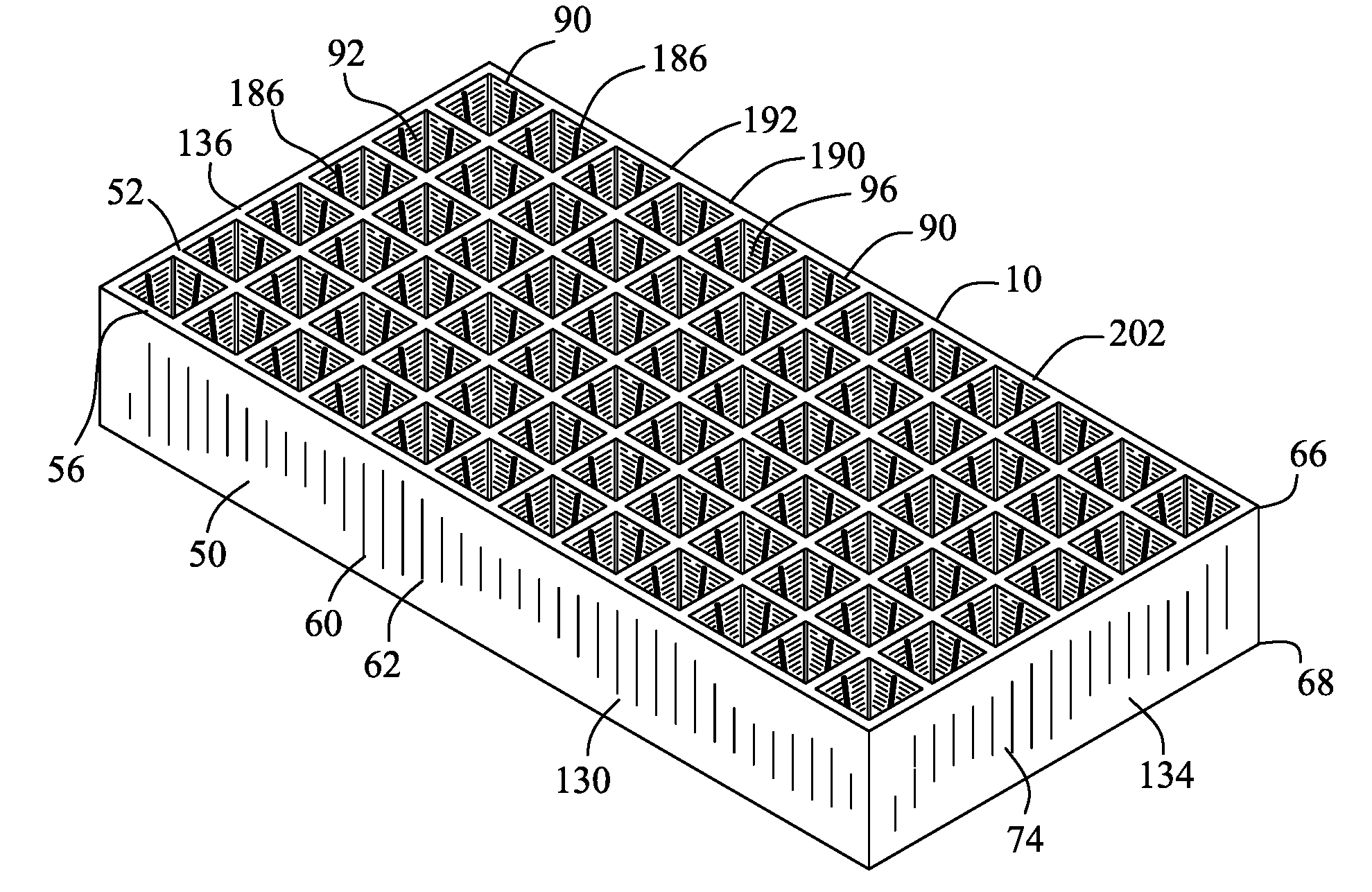
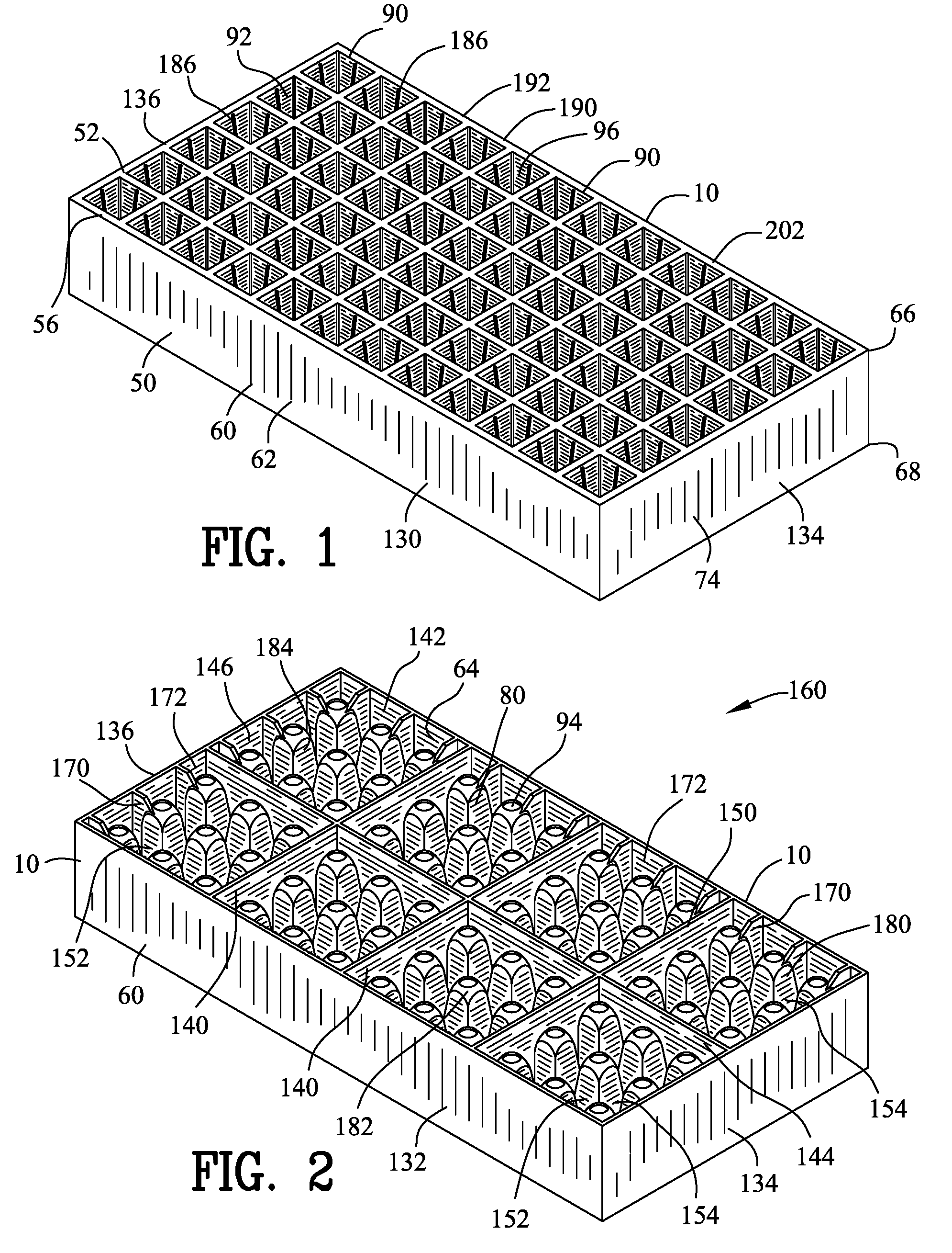
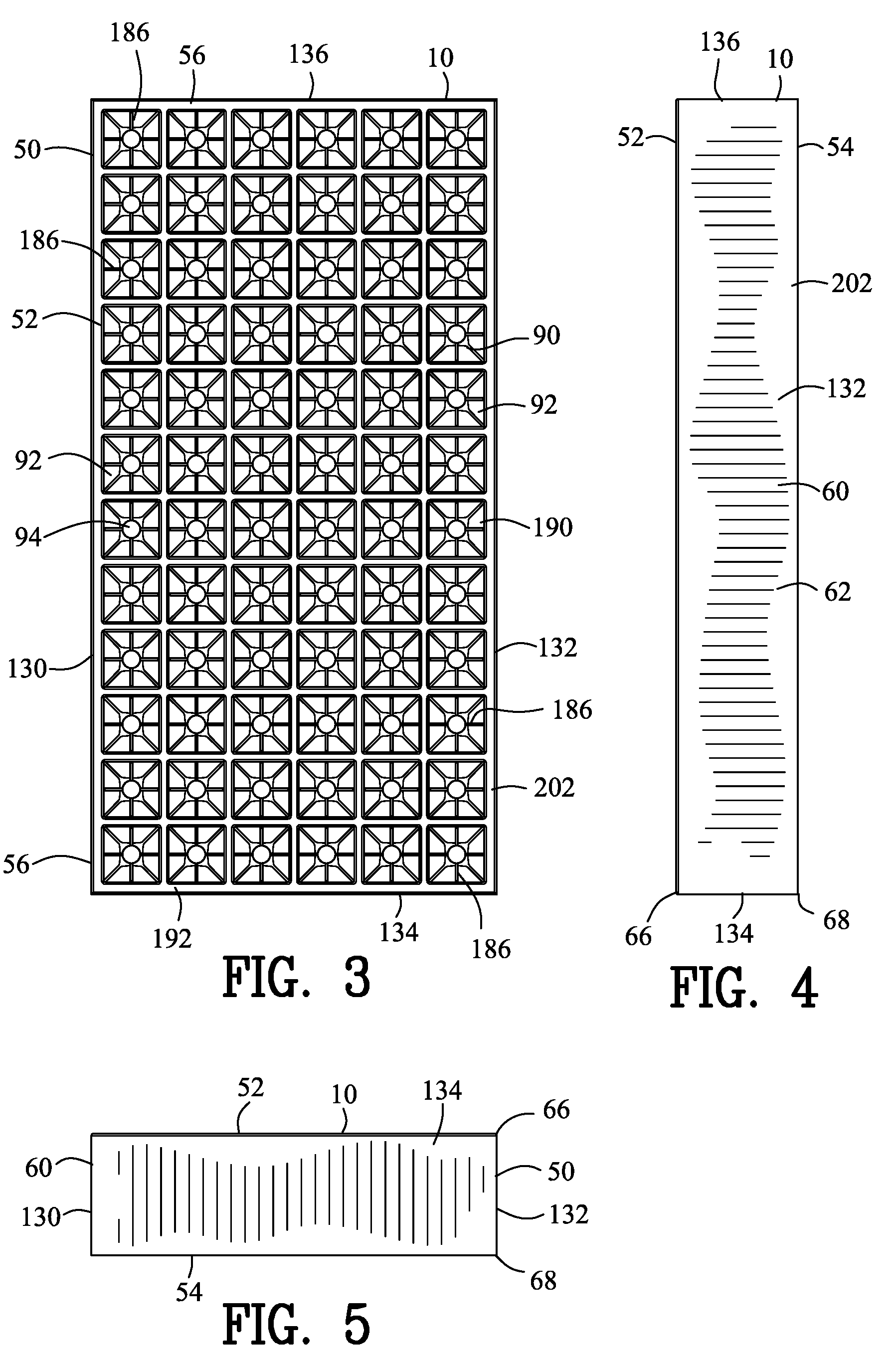
[0134]FIGS. 1-26 illustrate a floating plant propagation tray 10 for supporting soil 20, a plurality of seeds 22 and / or a plurality of seedlings 24. FIGS. 9-13 and FIGS. 22-26, illustrate the plurality of seedlings 24 including tobacco seedlings 26, however the plurality of seedlings 24 may include when any other type of plant propagule 28 from a seed.

[0135]The floating plant propagation tray 10 is preferably positioned within a body of fluid 30. The body of fluid 30 may include but not limited to an agricultural water tank 32, natural pond 34 or other bodies of water. The body of fluid to 30 includes a liquid surface 36 and a liquid depth 38. As shown in FIGS. 9-13 and 22-26, the floating plant propagation tray 10 is supported by the body of fluid 30.

[0136]The floating plant propagation tray 10 comprises a tray plate 50 including an upper surface 52, a lower surface 54 and a peripheral edge 56. A tray wall 60 includes an exterior surface 62, an interior surface 64, a proximal edge ...


PUM


Abstract

A floating plant propagation tray is supported by a body of fluid. The floating plant propagation tray comprises a tray plate, a tray wall and a plurality of soil cells. The proximal end of the plurality of soil cells define an upper soil cell aperture for receiving a soil and a plurality of seeds and / or a plurality of seedlings. The distal end of the plurality of soil cells include a lower soil cell aperture for inputting a portion of the body of fluid into the soil cell chamber. The plurality of soil cells extend within a tray chamber for defining a tray volume. The plurality of soil cell chambers define a cell volume. The cell volume and the tray volume define a buoyant equilibrium condition for supporting the floating plant propagation tray, the soil and the plurality of seeds and / or a plurality of seedlings within the body of fluid.

Description

BACKGROUND OF THE INVENTION[0001]1. Field of the Invention[0002]This invention relates to a plant growth tray and more particularly to a floating plant growth tray.[0003]2. Background of the Invention[0004]Plants are typically propagated in the horticultural industry from seeds, cuttings, tissue culture plantlets, etc (propagule) and propagated in specialist trays designed to produce the best quality plant most economically. These trays are typically divided into individual compartments to hold the soil (this can be peat, coir or many other types of substrate) and with a drain hole in the bottom of each compartment or cell. The trays are typically filled with soil and then the propagule is placed in the tray from which the transplant is grown. Plants are then removed from the tray and transplanted into a larger container or in the case of vegetable plants, tobacco plants, etc planted in the field soil. Some plant propagation systems use a float system where the propagation tray is f...

Claims


Application Information

Patent Timeline
IPC IPC(8): A01G9/10
CPCA01G9/104A01G31/02A01G9/0295Y02P60/21
Inventor COOLEY, JOHN N.MIGLIANTI, CHARLES G.
Owner INT PLANT PROPAGATION TECH LTD
Learn More