Transport vehicle and transport vehicle system

a technology for transport vehicles and transportation vehicles, applied in the direction of trolleys, mechanical conveyors, load-engaging elements, etc., can solve the problem that the overhead traveling vehicle cannot autonomously change the traveling direction, and achieve the effect of high flexibility in the path arrangemen

Active Publication Date: 2016-09-22
MURATA MASCH LTD
View PDF0 Cites 10 Cited by
  • Summary
  • Abstract
  • Description
  • Claims
  • Application Information

AI Technical Summary

Benefits of technology

[0010]In various preferred embodiments of the present invention, the traveling units on the front and the rear of the column or the traveling units on the right and the left thereof are supported by the paths, and the front and rear traveling units and the right and left traveling units are switched by the lifting mechanism. The lifting mechanism may, for example, raise one of the front and rear traveling units and the right and left traveling units, and lower the other thereof. Further, the lifting mechanism may raise and lower only one of the front and rear traveling units and the right and left traveling units, and fix the other thereof. Each of the traveling units includes the auxiliary wheels on the front and the rear of the traveling wheel, and the traveling unit is supported by the front and rear auxiliary wheels while the traveling wheel passes through the opening. This allows stable passing of the transport vehicle through the opening, and support of the transport by the column passing through the opening. The first path and the second path are able to be freely arranged longitudinally and transversely, thus leading to high flexibility in path arrangement. Further, this allows dense arrangement of the first path and the second path. The transport vehicle is able to exchange an article with a location immediately below the first path, a location immediately below the second path, and the like.
[0011]It is preferable that each of the at least the pair of first traveling units further include at least two guide rollers, which are located within the opening at the center of the first path and located in different positions from the center of the opening along a direction perpendicular or substantially perpendicular to a direction of the first path within a horizontal plane, and a first expansion / reduction mechanism that expands and reduces a space between the at least two guide rollers, each of the at least the pair of second traveling units further include at least two guide rollers, which are located within the opening at the center of the second path and located in different positions from the center of the opening along a direction perpendicular to a direction of the second path within the horizontal plane, and a second expansion / reduction mechanism that expands and reduces a space between the at least two guide rollers, and the space between the guide rollers of the lowered-side traveling unit out of the first traveling unit and the second traveling unit are expanded. By expanding the space between the guide rollers of the lowered-side traveling unit, the guide roller is guided by a guide surface such as a side surface of the path facing the opening, and by reducing the space between the guide rollers, the guide roller is able to be raised while avoiding sliding on the guide surface.
[0012]It is preferable that an interval between a wheel shaft of the first traveling wheel and a wheel shaft of each of the first auxiliary wheels on the front and the rear of the first traveling wheel is larger than a width of the opening in the second traveling path, and an interval between a wheel shaft of the second traveling wheel and a wheel shaft of each of the second auxiliary wheels on the front and the rear of the second traveling wheel is larger than a width of the opening in the first traveling path. In this manner, when the first traveling wheel passes through the opening, the first auxiliary wheels on the front and the rear of the first traveling wheel are supported by the treads, and when the second traveling wheel passes through the opening, the second auxiliary wheels on the front and the rear of the second traveling wheel are supported by the treads. This allows more stable traveling through the opening.
[0013]It is preferable that the first traveling units and the second traveling units are arranged to define a cross with the column at a center. In this manner, a load applied from the transport to the vehicle via the column is able to be stably supported, and the traveling units are present on the front and the rear and the right and the left of the crossing portion of the cross, thus allowing a traveling direction to be reliably changed.

Problems solved by technology

However, in JP2012-40961A, since a rail is mechanically rotated in a crossing portion of the cross, the overhead traveling vehicle cannot autonomously change a traveling direction.

Method used


Image

  • Transport vehicle and transport vehicle system
  • Transport vehicle and transport vehicle system
  • Transport vehicle and transport vehicle system

Examples


Embodiment Construction

[0023]Hereinafter, preferred embodiments of the present invention will be described. The scope of the present invention is to be set in accordance with understanding of a person skilled in the art, taking into consideration the description in the specification and the known techniques in this field.

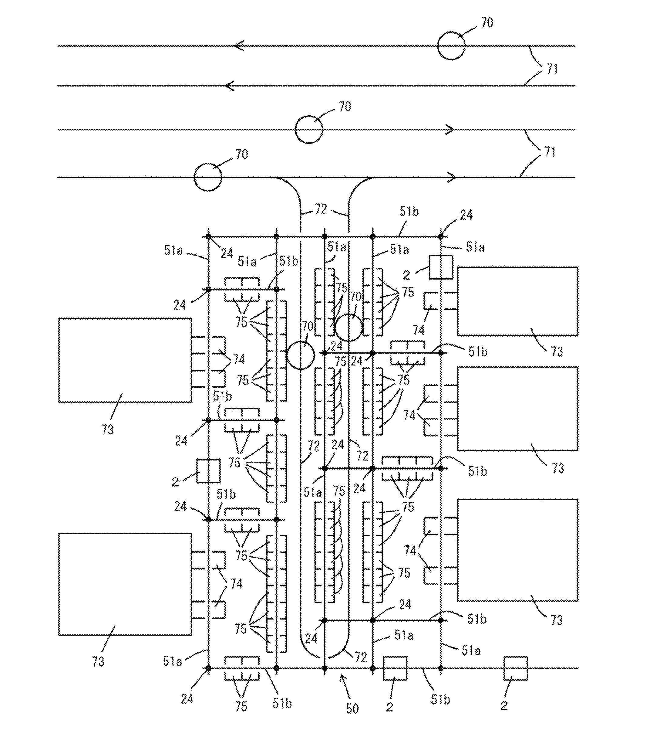
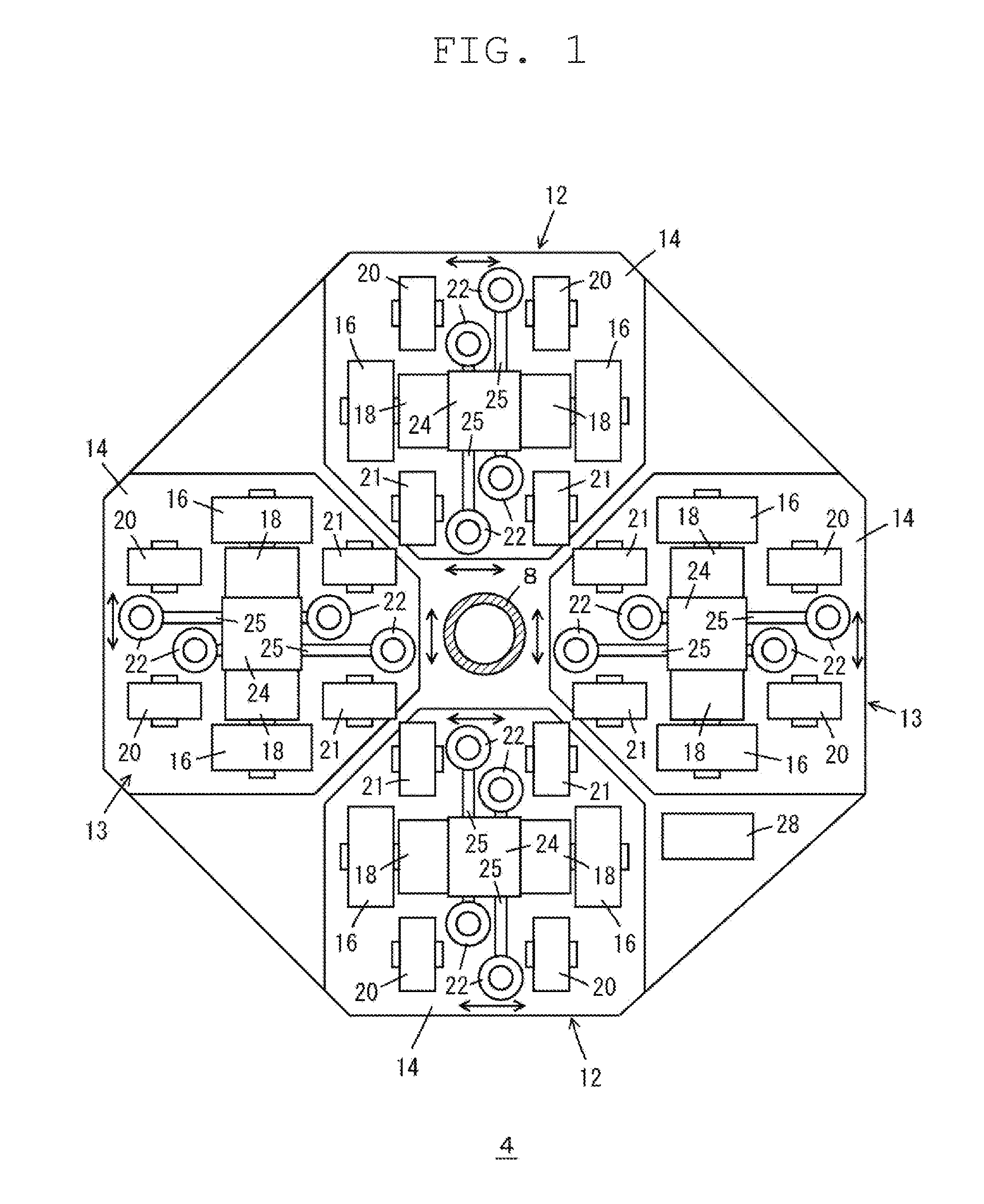
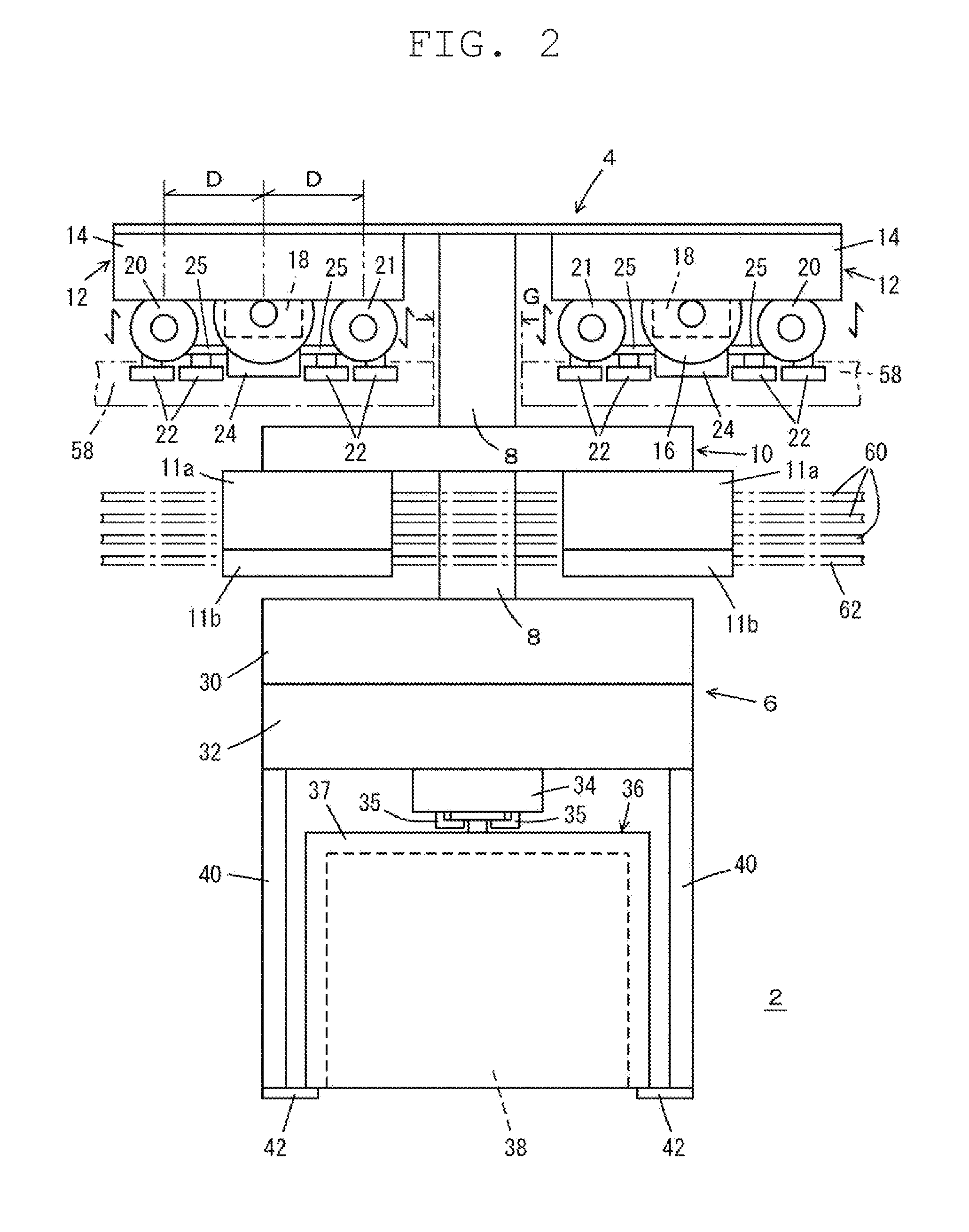
[0024]FIGS. 1 to 7 illustrate a transport vehicle 2 and a transport vehicle system according to a preferred embodiment of the present invention. FIG. 2 illustrates the transport vehicle 2 by a solid line, and a traveling path 50 by a chain line. FIGS. 3 and 4 illustrate a traveling path 50 by a solid line and the transport vehicle 2 by a chain line. The transport vehicle 2 preferably is a suspension-traveling type transport vehicle including a vehicle 4 that travels on the traveling path 50, and a transport 6 that is suspended from the vehicle 4 via a column 8 and moves below the traveling path 50. A power receiver 10 is provided between the vehicle 4 and the transport 6. The power receiv...


PUM


Abstract

A transport vehicle travels on first and second paths orthogonally or diagonally crossing each other and each including an opening at a center and treads on both sides of the opening. The transport vehicle includes a vehicle in an upper portion; a transport in a lower portion to hold an article; and a column extending downward from the vehicle to the transport. The vehicle includes on front and rear of the column along the first path, at least a pair of first traveling units each including a first traveling wheel that travels on the tread of the first path, and first auxiliary wheels on front and rear of the first traveling wheel along the first path; on front and rear of the column along the second path, at least a pair of second traveling units each including a second traveling wheel that travels on the tread of the second path, and second auxiliary wheels on front and rear of the second traveling wheel along the second path; and a lifting mechanism that raises and lowers one of the at least the pair of first traveling units and the at least the pair of second traveling units.

Description

BACKGROUND OF THE INVENTION[0001]1. Field of the Invention[0002]The present invention relates to a transport vehicle and a transport vehicle system.[0003]2. Description of the Related Art[0004]An overhead traveling vehicle system has been used for transport in a clean room or the like. JP2012-162096A describes that a branching portion and a merging portion are provided on a traveling route. JP2012-40961A describes that traveling routes for an overhead traveling vehicle are made to cross each other longitudinally and transversely. However, in JP2012-40961A, since a rail is mechanically rotated in a crossing portion of the cross, the overhead traveling vehicle cannot autonomously change a traveling direction.[0005]When the transport vehicle is enabled to travel while autonomously changing directions of longitudinal and transverse paths, it is possible to provide a large number of crossing portion of the cross of the paths. This allows dense arrangement of the paths, and also allows fr...

Claims


Application Information

Patent Timeline
Patent Type & Authority Applications(United States)
IPC IPC(8): B66C7/12B66C7/02B66C9/02B66C11/12
CPCB66C7/12B66C9/02B66C7/02B66C11/12B65G35/00B66C9/04H01L21/67733
Inventor IZUMI, TAKANORI
Owner MURATA MASCH LTD
Why Eureka
Try Eureka