Image forming apparatus and cartridge

a technology of image forming apparatus and cartridge, which is applied in the direction of electrographic process apparatus, instruments, optics, etc., can solve the problems of liability that a leakage image is generated, the photosensitive drum surface is liable to abrade, etc., and achieve the effect of lowering the light quantity and lowering the discharging ligh

Active Publication Date: 2016-09-22
CANON KK
View PDF4 Cites 0 Cited by
  • Summary
  • Abstract
  • Description
  • Claims
  • Application Information

AI Technical Summary

Benefits of technology

[0007]According to another aspect of the present invention, there is provided an image forming apparatus comprising: a rotatable image bearing member for carrying a toner image; a charging member for electrically charging the image bearing member; a transfer member for transferring the toner image from the image bearing member onto a transfer receiving member under application of a transfer voltage; a light source for emitting discharging light with which a surface of the image bearing member is irradiated to remove an electric charge remaining on the surface of the image bearing member after transfer of the toner image; and a light quantity lowering member for lowering a light quantity of the discharging light emitted from the light source to the image bearing member, wherein with respect to a rotational axis direction of the image bearing member, a charging region where the surface of the image bearing member is charged is broader than a transfer region where a current flows when a voltage is applied to the transfer member, and wherein with respect to the rotational axis direction of the image bearing member, the light quantity lowering member lowers the discharging light emitted from the light source to a region which includes end portions of the charging region of the surface of the image bearing member and which is inside the charging region and outside the transfer region, and does not lower the discharging light emitted from the direction to a region inside the transfer region.

Problems solved by technology

Here, with an increasing discharge amount, a photosensitive drum surface is liable to abrades.
When charging is made in a state in which the photosensitive layer is locally abraded, a current concentrates at a locally abraded portion and a region where the charging cannot be made generates at a periphery thereof, so that there is a liability that a leak image is generated.

Method used


Image

  • Image forming apparatus and cartridge
  • Image forming apparatus and cartridge
  • Image forming apparatus and cartridge

Examples


first embodiment

Image Forming Apparatus

[0021]A general structure of an image forming apparatus A according to First Embodiment of the present invention will be described together with an operation during image formation with reference to the drawings.

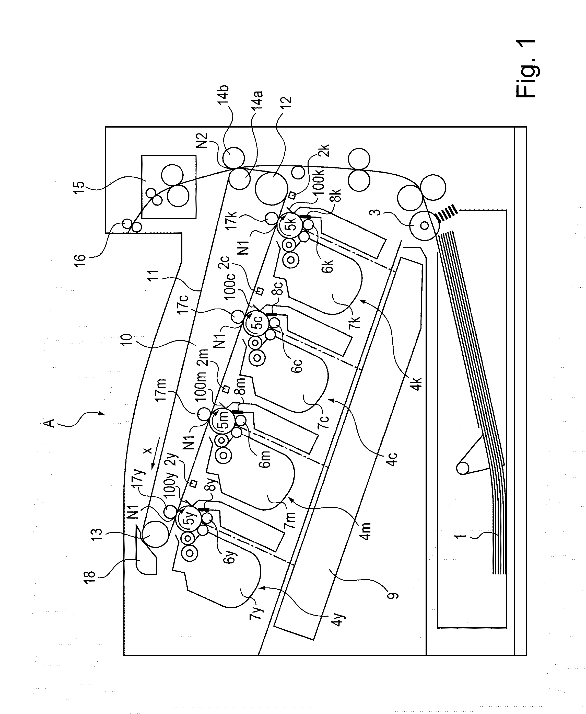
[0022]The image forming apparatus A according to this embodiment is a full-color laser printer employing a tandem type in which photosensitive drums are arranged in line and employing an intermediary transfer type. As shown in FIG. 1, the image forming apparatus A includes an image forming portion where a toner image is transferred onto a sheet, a feeding portion for supplying (feeding) the sheet to the image forming portion, and a fixing portion for fixing the toner image on the sheet.

[0023]The image forming portion includes a process cartridge 4 detachably mountable to a main assembly of the image forming apparatus A, intermediary transfer unit 10, a photosensitive drum (discharging means) 2, and a laser scanner unit 9.

[0024]The process cartridge 4 i...

modified embodiment

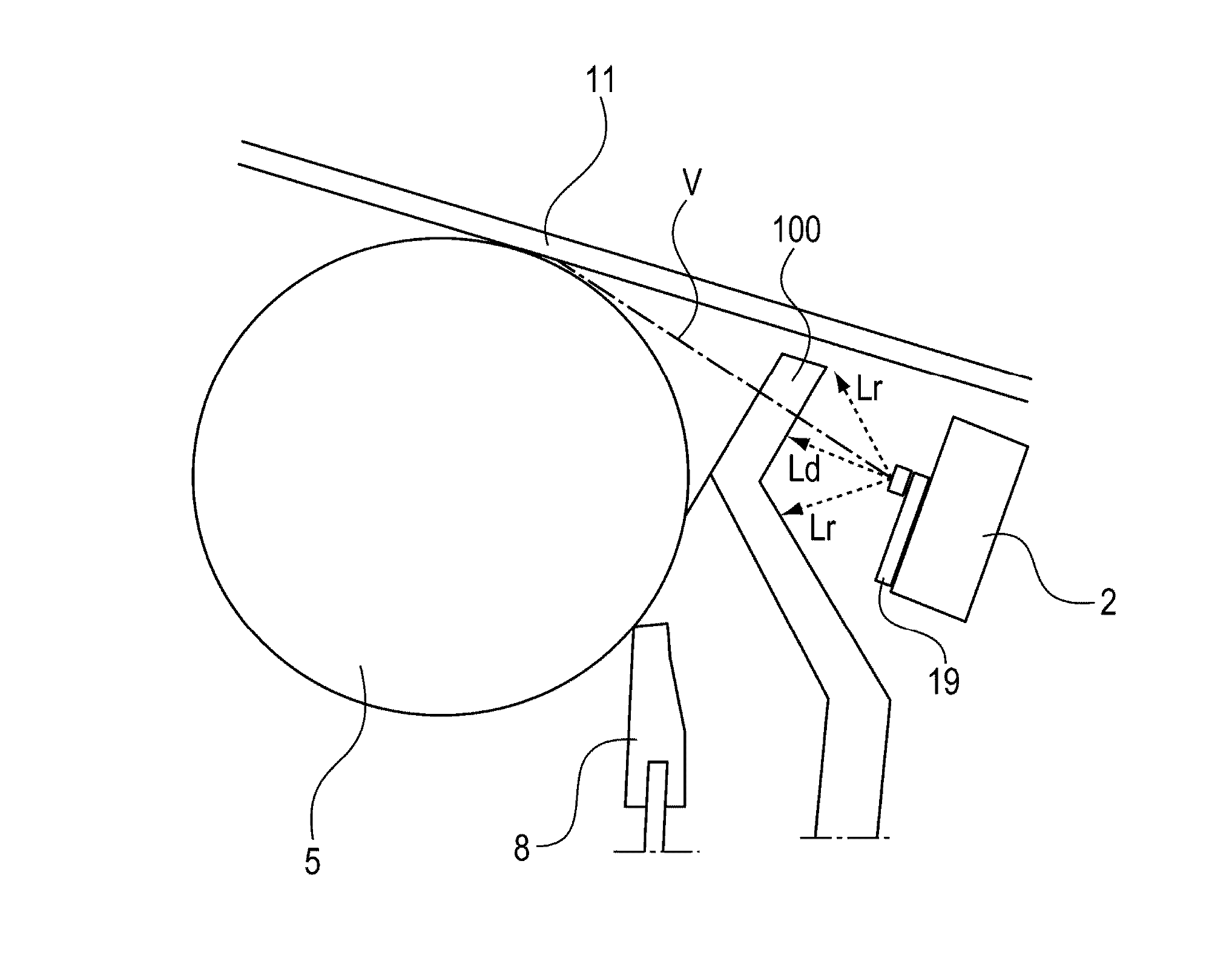
[0054]Next, as a modified embodiment of this embodiment, a constitution in which a shielding member 100 is bent at a position on an intermediary transfer belt 11 side with respect to the tangential line passing through the center of the light source and the surface of the photosensitive drum 5 will be described.

[0055]The shielding member 100 in the modified embodiment has a constitution, as shown in (a) of FIG. 5, in which the shielding member 100 is bent in an L-shape or a T-shape on the intermediary transfer belt 11 side with respect to the tangential line passing through the center of the light source 20 to the surface of the photosensitive drum 5. In a bending direction, the shielding member 100 is bent in the same direction as an optical path direction of the discharging light L from the light source 20 toward the end portions of the charging region Y.

[0056]Here, the optical path direction of the discharging light L from the light source 20 toward the end portions of the chargi...

second embodiment

Image Forming Apparatus

[0070]An image forming apparatus in this embodiment is similar to the image forming apparatus A in First Embodiment, and therefore will be omitted from description.

[0071]ATVC (active transfer voltage control) carried out during primary transfer in this embodiment will be described.

[0072]In the ATVC, first, during non-image formation, voltages subjected to constant-voltage control by controlling a transfer voltage source (voltage applying means) are applied to each of the primary transfer rollers 17 while changing an output voltage value. Then, from values of currents flowing at that time, resistance values of the primary transfer roller 17 and the intermediary transfer belt 11 are measured, and then a proper transfer voltage depending on the resistance value is applied to the primary transfer roller 17 when the toner image is transferred onto the sheet.

[0073]Specifically, first, the photosensitive drum 5 is charged by the charging roller 6 and thereafter as sh...


PUM


Abstract

An image forming apparatus includes a charging member, a light source, and a light quantity lowering member. The light quantity lowering member is provided so that a lowering amount of a quantity of a part of light reflected by a surface of a member at each of end portions of a charging region where the surface of the image bearing member is charged by the charging member is larger than that at a portion inside an associated end portion with respect to a rotational axis direction of the image bearing member.

Description

FIELD OF THE INVENTION AND RELATED ART[0001]The present invention relates to an image forming apparatus, such as an electrophotographic copying machine, an electrophotographic printer (e.g., a laser beam printer, an LED printer) or a facsimile machine, for forming an image on a recording material using an electrophotographic type, for example. The present invention also relates to a cartridge to be incorporated in the image forming apparatus.[0002]In an electrophotographic image forming apparatus, from the viewpoint of ozone suppression, as a charging member for electrically charging a photosensitive drum, a charging roller of a contact charging type in which an electroconductive member is contacted to the photosensitive drum to charge the photosensitive drum has been widely used. When the photosensitive drum is charged by this charging roller, electric discharge generates from the charging roller to the photosensitive drum. An amount of the discharge from an end portion of the char...

Claims


Application Information

Patent Timeline
Patent Type & Authority Applications(United States)
IPC IPC(8): G03G21/00
CPCG03G21/1803G03G15/04036G03G21/08G03G2215/0132
Inventor MASUI, KOICHIROYOSHIDA, NOBUYOSHI
Owner CANON KK
Why Eureka
Try Eureka