
Transmissive color liquid crystal display device

a liquid crystal display and color technology, applied in non-linear optics, instruments, optics, etc., can solve the problems of reducing contrast, deteriorating black in black display tightness, and losing optical activity, so as to reduce the light intensity of external light, enhance the contrast of displayed images, and reduce the light quantity of external reflecting light.

Inactive Publication Date: 2006-03-02
FUJIFILM CORP +1
View PDF3 Cites 6 Cited by
  • Summary
  • Abstract
  • Description
  • Claims
  • Application Information

AI Technical Summary

Benefits of technology

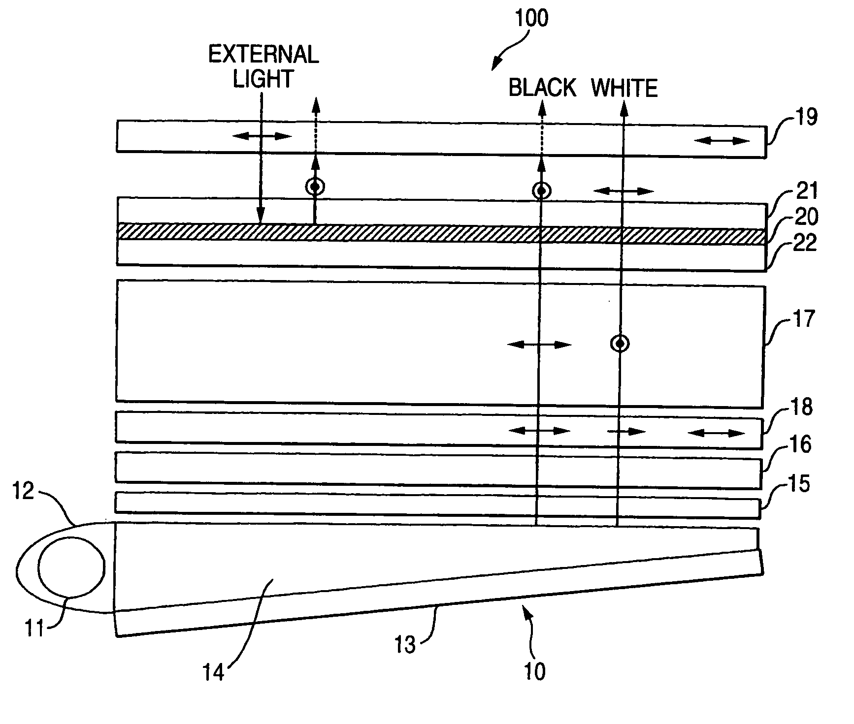
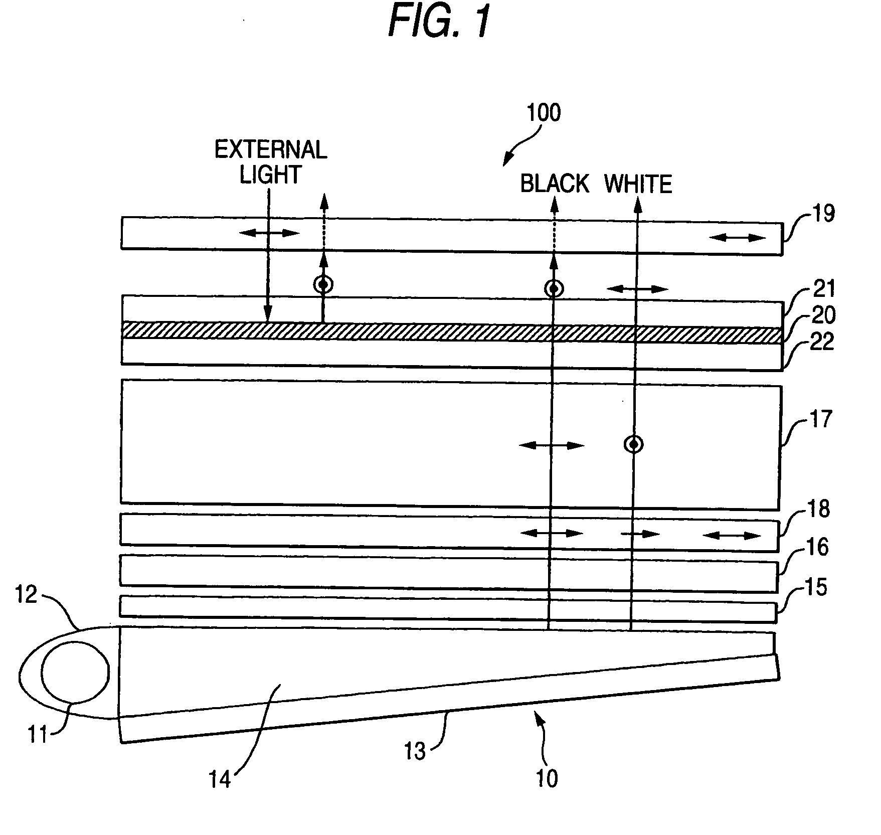
[0011] In view of the above circumstances, an object of this invention is to provide a transmissive color liquid crystal display device which can reduce the reflection on a color filter and further improve the contrast. (First Aspect)
[0017] For this reason, in the invention of (2), as the phase plate, a single ¼ wave plate (λ / 4 plate) is employed. When the linearly polarized light (external light) having passed through the upper polarizing plate passes through the ¼ wave plate twice, its polarization plane rotates by 90°. Thus, this light is the polarized light with the polarization plane orthogonal to the upper polarizing plate so that it cannot pass through the upper polarizing plate and does not return to the side of a viewer. In short, the reflection can be prevented surely.
[0019] (5) A transmissive color liquid crystal display device comprising a lower polarizing plate on a light source side, an upper polarizing plate on a display side, a liquid crystal panel arranged between the lower polarizing plate and the upper polarizing plate, and a color filter arranged between the liquid crystal panel and the upper polarizing plate, further comprising a member for reducing light intensity of external light passing through the upper polarizing plate and reflecting at the color filter, which is arranged between the upper polarizing plate and the color filter.
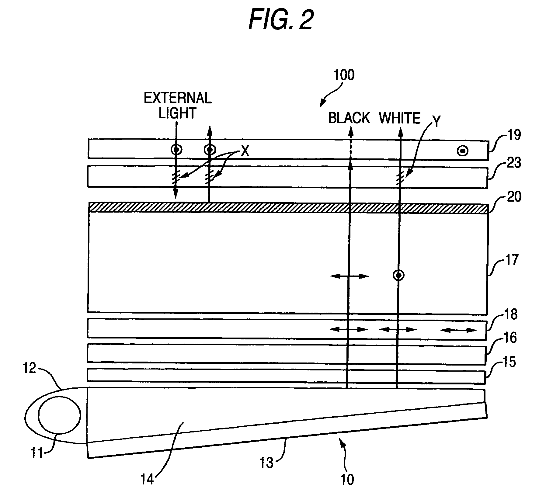
[0022] In accordance with the second aspect of this invention, between the upper polarizing plate and the color filter, a member is arranged for reducing light intensity of external light passing through the upper polarizing plate and reflecting at the color filter. This can reduce the influence of the reflecting light entering the view's eyes, thereby permitting the contrast of a displayed image to be enhanced. For example, where the ND filter (light quantity reducing filter) is employed, the reflecting light on the color filter when the external light is incident passes through the ND filter twice so that the light quantity is reduced by the quantity proportional to twice of the thickness of the ND filter (ND layer). On the other hand, the incident light from the backlight for forming an image passes only once through the ND filter, the light quantity is reduced by only once of the thickness of the ND filter (ND layer). Thus, as compared with reduction in the light quantity employed for image display, the light quantity of the reflecting light of the external light can be reduced twice. This leads to the liquid crystal display with high contrast. Incidentally, if the reduction in the light quantity for image display by the ND filter is compensated for by an increase in the light quantity from the backlight, influence of the reduction in the light quantity for display can be eliminated.

Problems solved by technology

Further if the applied voltage becomes further high, the optical activity will be eventually lost so that the linearly polarized light having passed through the polarizing plate on the light incidence side reaches the polarizing plate on the light emission side without optically rotating.
Meanwhile, such a liquid crystal display device presented a problem that since the external light in the room or from a window reflects from an image display plane, tightness of black in black display deteriorates to decrease the contrast.
However, where the low reflectance film is bonded to suppress the surface reflectance at the air interface to a certain degree or lower, the latter internal reflection on the color filter surface, particularly the reflection on the black matrix surface has relatively led to a new problem in improving the contrast.
However the countermeasure for the internal reflection on the color filter has not been carried out sufficiently.

Method used


Image

  • Transmissive color liquid crystal display device
  • Transmissive color liquid crystal display device
  • Transmissive color liquid crystal display device

Examples


example

[0058] The advantage of the second aspect of this invention will be verified below referring to an example.

[0059] A transmissive color liquid crystal display device (referred to as device A2) which is manufactured to have the configuration shown in FIG. 2 was prepared as an example. A transmissive color liquid crystal device (referred to as device B2) which is manufactured to have the configuration shown in FIG. 2 but not equipped with the ND filter 23 was prepared as a comparative example. In device A2, in order to remove the reflection on the surface with respect to the measurement of the reflectance, the upper polarizing plate 19 was made apart from the ND filter 23. In this case, the degree of being apart was determined as follows. Namely, where the light source is located at 45° from the normal line to the image display plane, the position was empirically determined which permits the regular reflection on the upper polarizing plate 19 and that on the color filter 20 to be meas...


PUM

PropertyMeasurementUnit
rotation angleaaaaaaaaaa
incident angleaaaaaaaaaa
brightnessaaaaaaaaaa

Abstract

A transmissive color liquid crystal display device includes a liquid crystal layer arranged a lower polarizing plate on a light source side and an upper polarizing plate on a display side, the liquid crystal layer changing a polarization plane of linearly polarized light having passed through the lower polarizing plate to adjust light transmittance, a color filter arranged between the liquid crystal layer and the upper polarizing plate, a 1 / 4 phase plate arranged between the upper polarizing plate and the color filter for rotating a polarization plane of external light passing through the upper polarizing plate and reflecting at the color filter to 90° permitting the upper polarizing plate to absorb the external light, and another 1 / 4 phase plate arranged beneath the color filter. Further, another transmissive color liquid crystal display device includes a liquid crystal layer arranged a lower polarizing plate on a light source side and an upper polarizing plate on a display side, the liquid crystal panel changing a polarization plane of linearly polarized light having passed through the lower polarizing plate to adjust light transmittance, a color filter arranged between the liquid crystal panel and the upper polarizing plate, and an ND filter arranged between the upper polarizing plate and the color filter.

Description

[0001] This application is based on Japanese Patent applications JP 2004-246269 and JP 2004-246270, both filed Aug. 26, 2004, the entire contents of which are hereby incorporated by reference. This claim for priority benefit is being filed concurrently with the filing of this application. BACKGROUND OF THE INVENTION [0002] 1. Technical Field of the Invention [0003] This invention relates to a transmissive color display liquid crystal display device capable of reducing reflection of external light to increase the contrast of a displayed image. [0004] 2. Description of the Related Art [0005] At present, as a display for various apparatus, transmissive color liquid crystal display devices are being widely employed. Among them, the liquid crystal display device in a TN (Twisted Nematic) mode which is generally widely used has a structure in which a liquid crystal layer is formed of liquid crystal molecules sealed in a twisted state by 90° between two glass substrates having transparent ...

Claims


Application Information

Patent Timeline
Patent Type & Authority Applications(United States)
IPC IPC(8): G02F1/1335
CPCG02F1/133509G02F1/13363G02F2413/07G02F2001/133638G02F2413/02G02F2001/133562G02F1/133562G02F1/133638
Inventor ARAI, HISAO
Owner FUJIFILM CORP
Learn More