
Field sequential color liquid crystal display device and color control method thereof

a liquid crystal display and color control technology, applied in the field of liquid crystal display technology, can solve the problems of low efficiency of generating red light by excitation of green light, and achieve the effects of improving the production capacity of the liquid crystal display panel, reducing the cost of production, and increasing the aperture ratio

Active Publication Date: 2016-09-22
TCL CHINA STAR OPTOELECTRONICS TECH CO LTD
View PDF4 Cites 5 Cited by
  • Summary
  • Abstract
  • Description
  • Claims
  • Application Information

AI Technical Summary

Benefits of technology

The present invention is a color liquid crystal display device and method that uses only two types of color sub-pixels, improving production capacity of the display panel while achieving larger aperture ratio and higher transmittance compared to conventional devices with the same resolution. Additionally, the backlight module only uses one type of LED formed by the red and blue chips and the green phosphor, allowing for individual switching of colors and achieving a high color gamut after adoption of this LED. Compared to conventional LED of RGB chips, the amount of LED is reduced, making it easier to achieve a narrow border design.

Problems solved by technology

However, in the light emitting diode constituted by the blue light emitting chip and the red and green phosphors, besides the red phosphor and the green phosphor absorb the blue light and then are excitated to respectively emit red light and green light, a small amount of the red phosphor will absorb the green light and then is excitated to emit red light, but the efficiency of generating the red light by the excitation of the green light is low, which also is an important reason of the brightness of the light emitting diode constituted by the blue light emitting chip and the red and green phosphors being low.

Method used


Image

  • Field sequential color liquid crystal display device and color control method thereof
  • Field sequential color liquid crystal display device and color control method thereof
  • Field sequential color liquid crystal display device and color control method thereof

Examples


Embodiment Construction

[0022]In the following, various embodiments of the present invention will be described in detail with reference to accompanying drawings. The present invention may be embodied in many different forms and should not be construed as limiting to the embodiments set forth herein. Rather, these embodiments are provided to explain the principles of the present invention and its practical applications, so that other skilled in the art can understand various embodiments of the present invention and various modifications suitable for specific intended applications.

[0023]In the drawings, the same reference numerals will be used throughout the drawings to refer to the same or like components. It is understood that, although the terminologies such as “first”, “second”, “third”, “fourth” can be used herein to describe various components, these components should not be limited by the terminologies. These terminologies are only used to distinguish one component from another component.

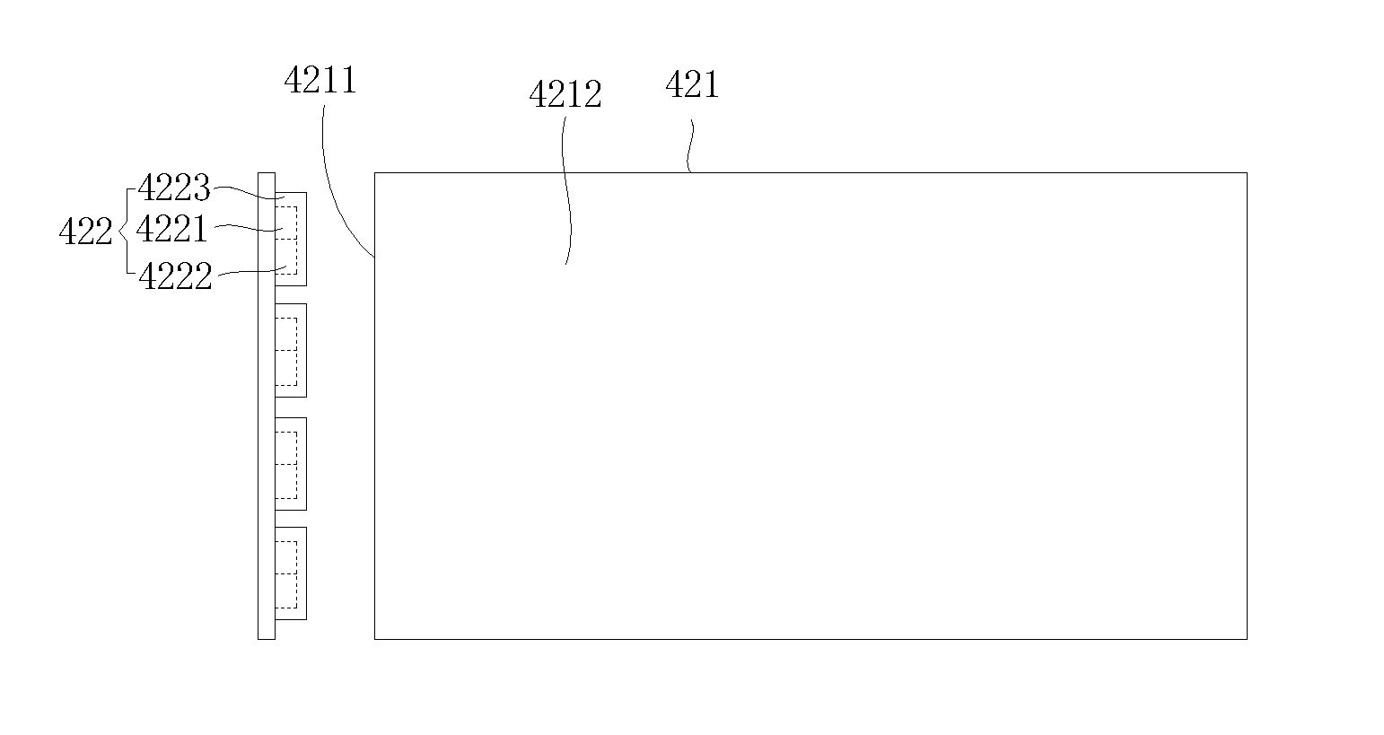
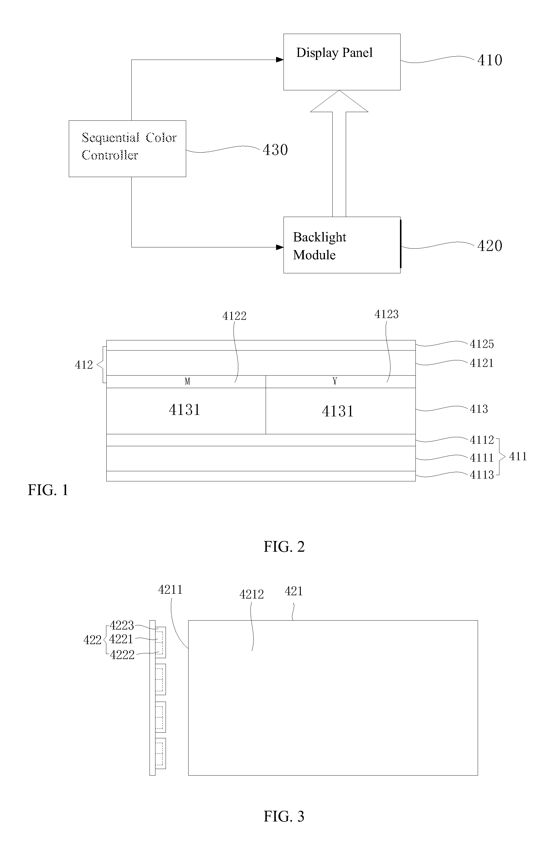
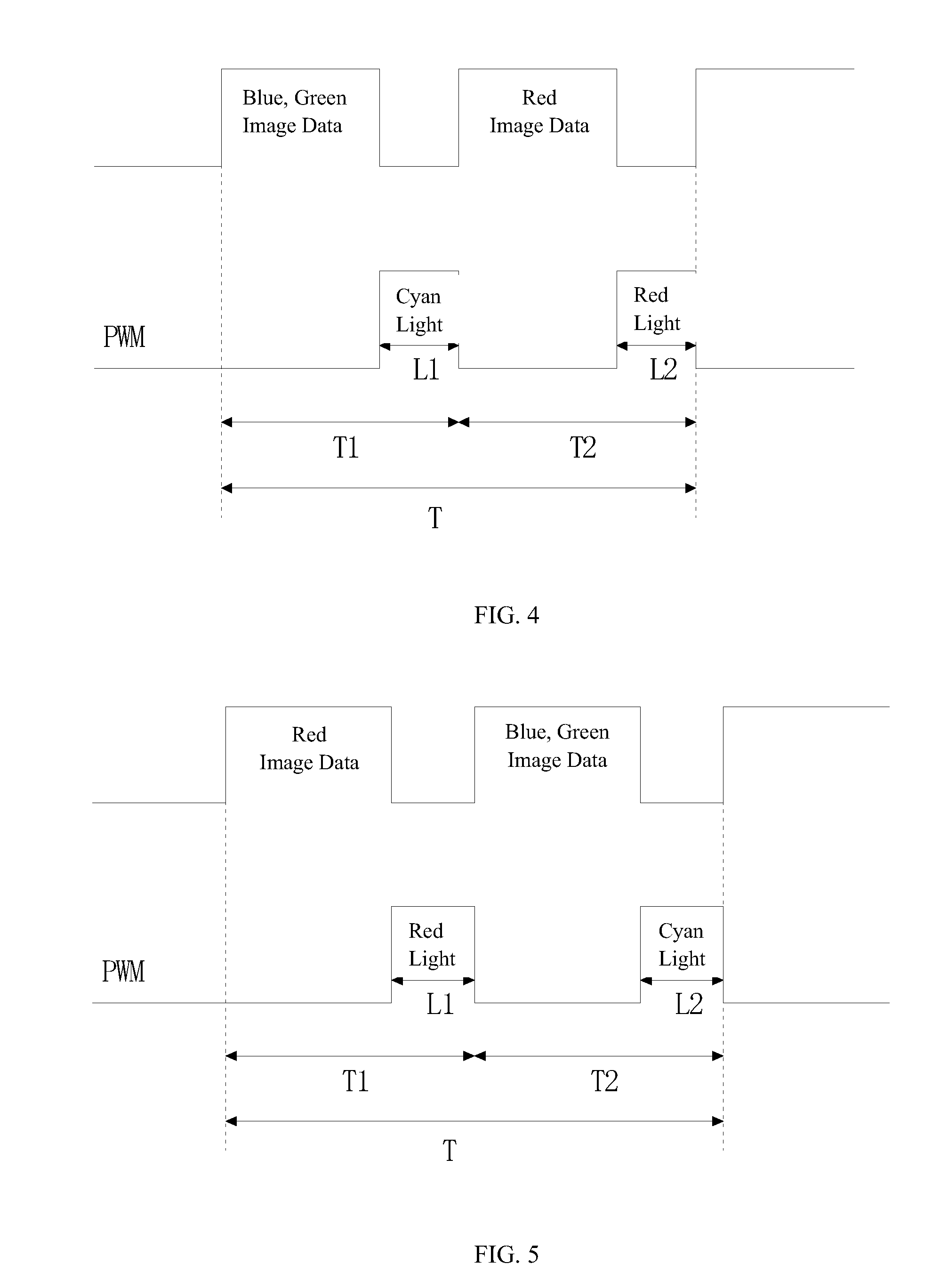
[0024]FIG. 1 ...


PUM

PropertyMeasurementUnit
color fieldaaaaaaaaaa
color imageaaaaaaaaaa
pulse widthaaaaaaaaaa

Abstract

A field sequential color liquid crystal display (FSC-LCD) device and a color control method thereof are provided. The FSC-LCD device includes: a liquid crystal display panel which includes a color filter of first color sub-pixel and a color filter of second color sub-pixel, and a color field period thereof is sequentially divided into a first sub-color-field period and a second sub-color-field period; and a backlight module for providing a backlight source to the liquid crystal display panel and including a red backlight and a cyan backlight. The backlight module is for providing two color backlights respectively during a first backlighting period in the first sub-color-field period and a second backlighting period in the second sub-color-field period. The present FSC-LCD device has larger aperture ratio and higher transmittance, can achieve high color gamut display, and is easily to realize the narrow border design while reducing the amount of LED.

Description

TECHNICAL FIELD[0001]The present invention relates to the field of liquid crystal display technology, and particularly to a field sequential color liquid crystal display device and a color control method thereof.DESCRIPTION OF RELATED ART[0002]With the development of electro-optical and semiconductor technologies, the development of flat panel display devices is promoted. In various types of flat panel display devices, the liquid crystal display device has becoming a mainstream of market owing to its superior characteristics of high space utilization efficiency, low power consumption, radiation free and low electromagnetic interference, and so on.[0003]The liquid crystal display device generally includes a liquid crystal display panel and a backlight module. Since the non-self-emissive characteristic of the liquid crystal display panel, it is necessary to dispose the backlight module below the liquid crystal display panel to provide a surface light source for the liquid crystal disp...

Claims


Application Information

Patent Timeline
Patent Type & Authority Applications(United States)
IPC IPC(8): G09G3/34F21V8/00G02F1/1335G09G3/20G09G3/36
CPCG09G3/3413G09G3/2003G09G3/342G09G3/3607G09G3/3648G02F1/133514G02F2001/133622G02F1/133621G02B6/0068G02B6/0073G09G2300/0452G02F2001/133302G02F1/1368G02F1/133528G02F1/133622G02F1/133302G09G3/36
Inventor FAN, YONG
Owner TCL CHINA STAR OPTOELECTRONICS TECH CO LTD
Learn More