Light emitting device and illumination device
- Summary
- Abstract
- Description
- Claims
- Application Information
AI Technical Summary
Benefits of technology
Problems solved by technology
Method used
Image

Examples
embodiment 1
Configuration of Illumination Device 1
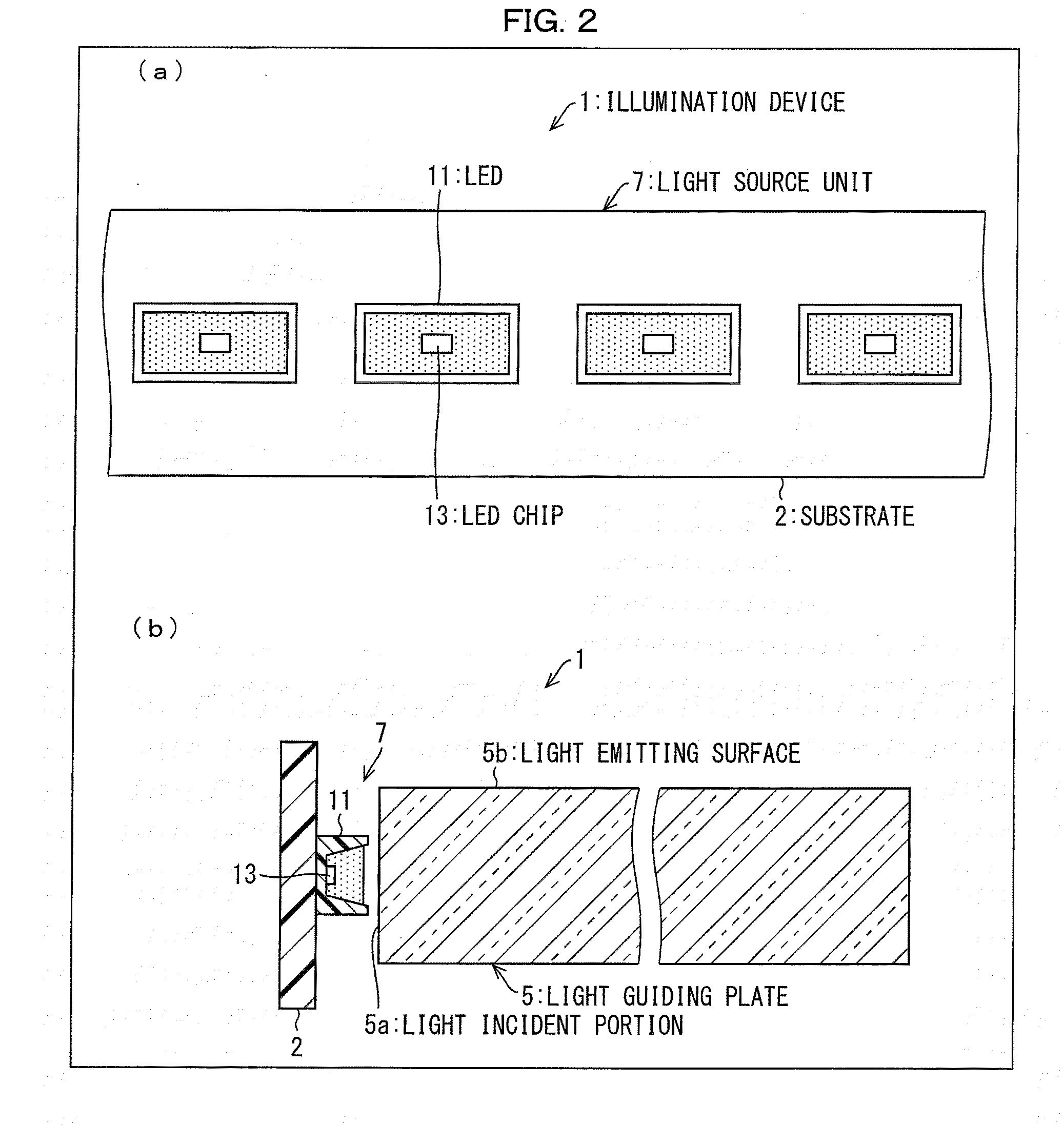
[0041]First, the illumination device 1 which uses an LED (light emitting device) 11 according to the present embodiment will be described. FIG. 2(a) is an expanded plan view illustrating a part of the illumination device 1 which uses the LED 11 according to Embodiment 1, and FIG. 2(b) is a sectional view of the illumination device 1 illustrated in FIG. 2(a).
[0042]As illustrated in FIGS. 2(a) and 2(b), the illumination device 1 includes a substrate 2, multiple LEDs 11 and a light guiding plate 5. The illumination device 1 also includes an LED drive control unit (refer to FIG. 3), which is not illustrated in FIG. 2, for controlling driving of multiple LEDs 11.
[0043]The light guiding plate 5 has a rectangular shape overall and is a transparent member having a predetermined thickness. The light guiding plate 5 has a structure in which light is emitted from each portion of a light emitting surface 5b such that light which is incident from a light inc...
embodiment 2
[0156]A second embodiment of the present invention will be described as follows with reference to FIG. 13 to FIG. 16. In addition, for the sake of convenience of description, the same symbols will be attached to the members having the same functions as the members described in the embodiment 1, and description thereof will be omitted.
[0157]FIG. 13(a) is an expanded plan view illustrating a part of a light source unit 37 in an illumination device 31 according to embodiment 2, and FIG. 13(b) is a sectional view of the illumination device 31.
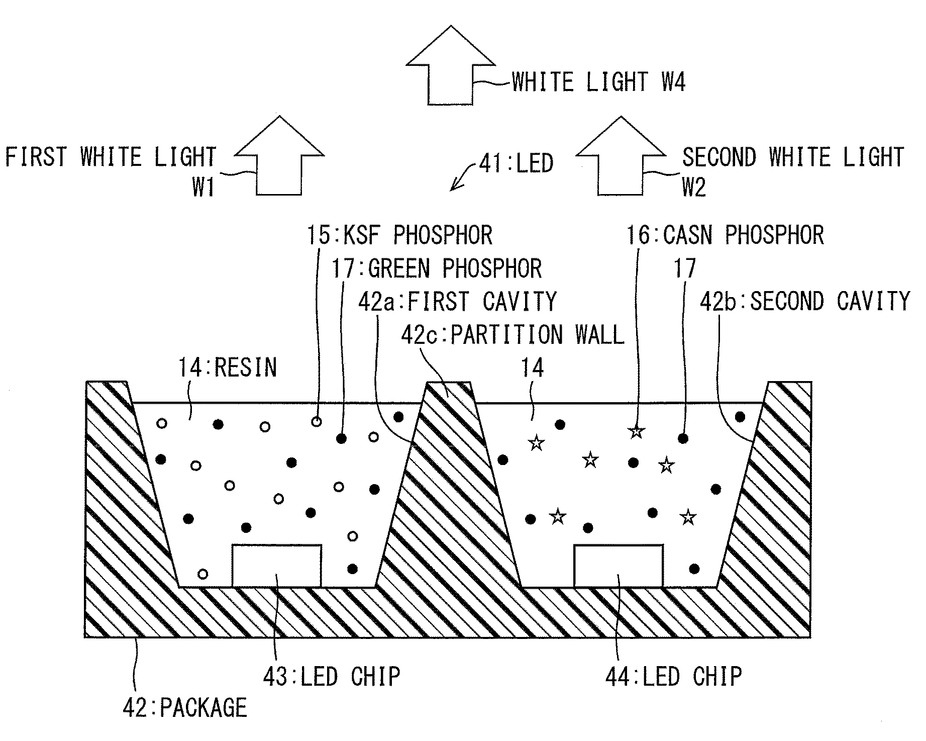
[0158]As illustrated in FIGS. 13(a) and 13(b), the illumination device 31 includes the substrate 2, multiple LEDs (light emitting device) 41, and the light guiding plate 5. In addition, the illumination device 31 also includes an LED drive control unit (refer to FIG. 15), which is not illustrated in FIG. 13, for controlling drive of the multiple LEDs 41.
[0159]The multiple LEDs 41 are mounted on the substrate 2 so as be lined up in one line in a lon...
embodiment 3
[0208]A third embodiment of the present invention will be described as follows. In addition, for the sake of convenience of description, the same symbols will be attached to the members having the same functions as the members described in the embodiments 1 and 2, and description thereof will be omitted.
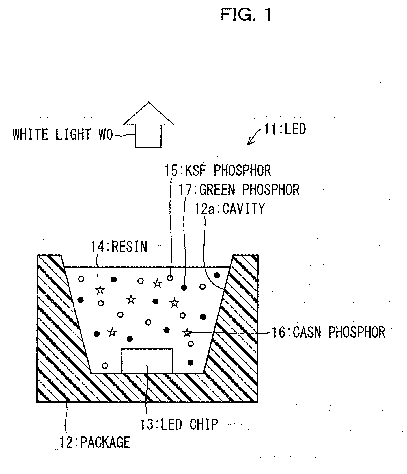
[0209]In a case of a drive state in which duty of the signal which is used in the LED 11 (refer to FIG. 1) described in embodiment 1 or the LED 41 (refer to FIG. 14) described in embodiment 2 is equal to or less than 50%, the mixture ratio of the KSF phosphor 15 and the CASN phosphor 16 is adjusted according to the frequency of the PWM signal. Accordingly, it is possible to improve video quality of a display device such as a liquid crystal television which uses the LED 11 or the LED 41.
[0210](a) When the frequency (frame frequency) of the PWM signal is equal to or higher than 60 Hz and lower than 120 Hz
[0211]In the display device, the frequencies (frame frequencies) of the PWM signal...
PUM
 Abstract
Description
Claims
Application Information
 - Generate Ideas
- Intellectual Property
- Life Sciences
- Materials
- Tech Scout
- Unparalleled Data Quality
- Higher Quality Content
- 60% Fewer Hallucinations
Browse by: Latest US Patents, China's latest patents, Technical Efficacy Thesaurus, Application Domain, Technology Topic, Popular Technical Reports.
© 2025 PatSnap. All rights reserved.Legal|Privacy policy|Modern Slavery Act Transparency Statement|Sitemap|About US| Contact US: help@patsnap.com