Method and arrangement for waste cold recovery in a gas-fuelled sea-going vessel

a gas-fuelled sea-going vessel and waste cold technology, applied in the direction of liquid fuel feeders, machines/engines, container discharge methods, etc., can solve the problems of double all pump-related costs, a number of relatively expensive equipment, and a relative complicated structure, so as to simplify the work arrangement in the building of the ship

Active Publication Date: 2016-09-29
WARTSILA FINLAND OY
View PDF0 Cites 10 Cited by
  • Summary
  • Abstract
  • Description
  • Claims
  • Application Information

AI Technical Summary

Benefits of technology

[0010]According to an aspect of a present invention there is provided a fuel storage and distribution system for a sea-going vessel, which enables cutting manufacturing costs and constructional complexity in comparison to prior art systems. According to another aspect of a present invention there is provided a fuel storage and distribution system that enables using cold gas fuel effectively to absorb heat from an HVAC system of the vessel. According to a further aspect of the invention there is provided a fuel storage and distribution system that enables flexibly controlling the heat flows between the HVAC and engine cooling systems of the vessel and the gas fuel. According to yet another aspect of the invention there is provided a method for transferring heat from the HVAC system of the vessel to gas fuel of said vessel in an efficient and flexible manner.
[0015]The invention makes it possible to eliminate a number of the pumps and other components of prior art systems by making a part of a refrigeration or air conditioning circuit reach into the tank room. A local heat transfer circuit in the tank room may extract heat from said part of a refrigeration or air conditioning circuit and donate such heat further to the gas fuel either directly or indirectly. Significant portions of the fuel storage and distribution system can be constructed as a module that is delivered to the shipyard as a completed entity, which cuts construction times and simplifies work arrangements in building the ship.

Problems solved by technology

Additionally they often include relatively complicated structures and a number of relatively expensive equipment.
Maritime classification requirements typically require doubling the pumps to achieve reliability through redundancy, which doubles all pump-related costs.

Method used


Image

  • Method and arrangement for waste cold recovery in a gas-fuelled sea-going vessel
  • Method and arrangement for waste cold recovery in a gas-fuelled sea-going vessel
  • Method and arrangement for waste cold recovery in a gas-fuelled sea-going vessel

Examples


Embodiment Construction

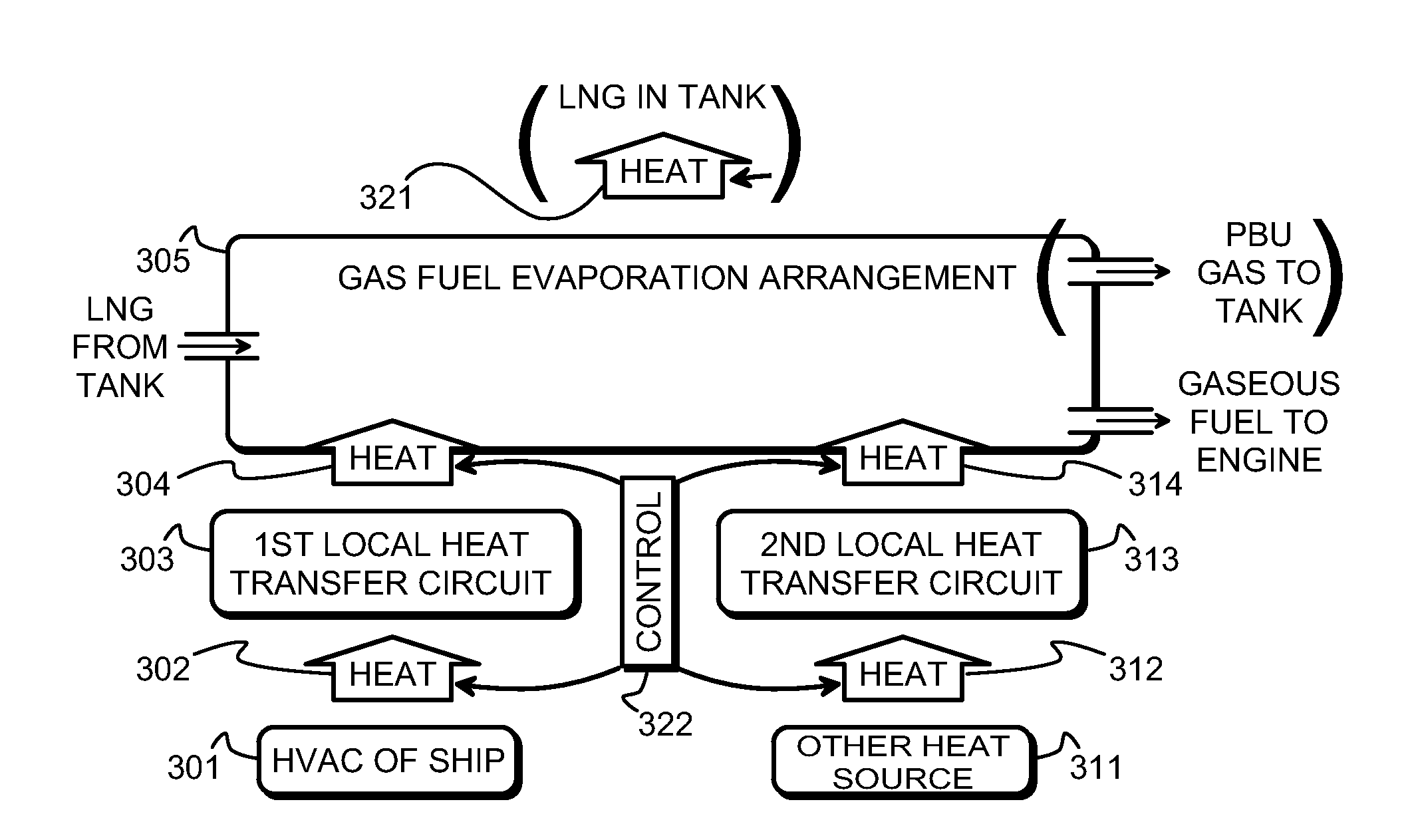
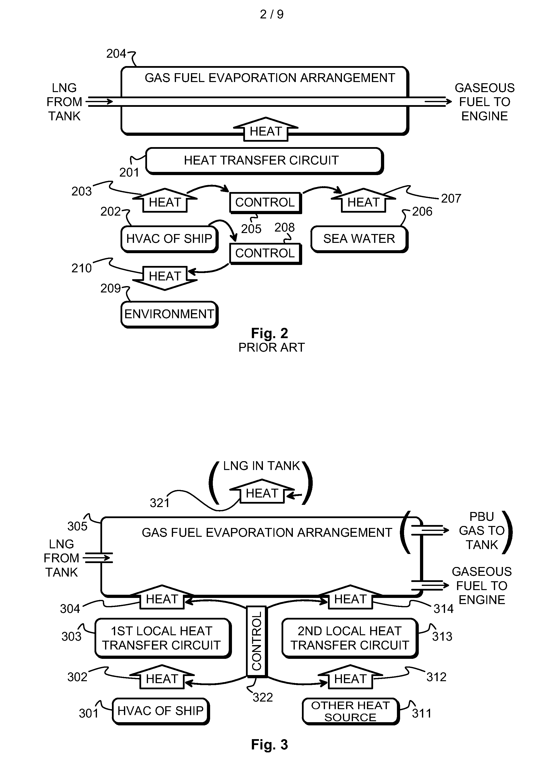
[0028]FIG. 3 illustrates some material and heat flows in a fuel storage and distribution system according to an embodiment of the invention. Block 301 represents generally HVAC systems, or systems that are used on board the vessel to produce and maintain temperatures that are below ambient temperature. Examples of what the HVAC system block 301 may comprise are air conditioning of cabins, lounges, restaurants, and other internal spaces; refrigeration of cold stores and other storage rooms; refrigeration of cargo holds or individual containers; and cooling of potable water.

[0029]Arrow 302 shows how heat is transferred from the HVAC systems to a heat transfer circuit, which is called the first local heat transfer circuit 303. Arrow 304 shows how the first local heat transfer circuit 303 is arranged to transfer such received heat to liquefied gas fuel that is handled in the fuel storage and distribution system. Conceptually the last-mentioned transfer takes place within a gas fuel evap...


PUM


Abstract

A fuel storage and distribution system for a gas-fueled sea-going vessel comprises a tank room that constitutes a gastight space enclosing tank connections and valves associated with them. A part of a refrigeration or air conditioning circuit reaches into said tank room. A first local heat transfer circuit is configured to receive heat from said part of the refrigeration or air conditioning circuit in said tank room and arranged to transfer such received heat to liquefied gas fuel handled in said fuel storage and distribution system.

Description

TECHNICAL FIELD[0001]The invention concerns in general the technology of arranging the heat and material flows in and in association with the fuel storage and distribution system of a gas-fuelled sea-going vessel. Especially the invention concerns utilizing the fuel storage and distribution system to absorb heat from the HVAC (heating, ventilation, and air conditioning) system of the vessel.BACKGROUND OF THE INVENTION[0002]In US patent publication 2903860 is disclosed a fuel storage and distribution system for a gas-fuelled sea-going vessel, comprising a gas tank for storing gas fuel, a major portion of which is in liquefied form; a tank room that constitutes a gastight space enclosing tank connections to and from the tank room and valves associated with them; a part of a refrigeration or air conditioning circuit reaching into said tank room, a first local heat transfer circuit in the tank room, which first local heat transfer circuit is configured to receive heat from said part of ...

Claims


Application Information

Patent Timeline
Patent Type & Authority Applications(United States)
IPC IPC(8): F17C9/04F02M37/00
CPCF17C9/04F17C2270/0105F02M37/0082F02M37/007B63B2770/00F17C2203/03F17C2205/0323F17C2223/0153F17C2221/033F17C2223/033F17C2227/0107F17C2227/0309F17C2227/0327F17C2227/0332F17C2250/0439F17C2265/066F02M37/0017F17C2203/0391F17C2205/0111F17C2205/0326F17C2205/0355F17C2223/0161F17C2223/035F17C2223/041F17C2223/046F17C2227/0316F17C2227/0323F17C2227/0372F17C2227/0374F17C2227/0379F17C2250/032F17C2250/0408F17C2250/043F17C2250/0491F17C2250/0631F17C2250/0636F17C2260/011F17C2260/042
Inventor KARLSSON, SOREN
Owner WARTSILA FINLAND OY
Why Eureka
Try Eureka