
Mobile Renewable Energy Light Tower

a renewable energy and light tower technology, applied in the field of portable renewable energy light towers, can solve the problems of increasing the cost of using lights, producing unwanted noise and pollution, and needing temporary or emergency electrical power, and achieves the effects of increasing stability, increasing safety and stability, and convenient loading and unloading

Inactive Publication Date: 2016-09-29
CARPOFF JEFF
View PDF8 Cites 13 Cited by
  • Summary
  • Abstract
  • Description
  • Claims
  • Application Information

AI Technical Summary

Benefits of technology

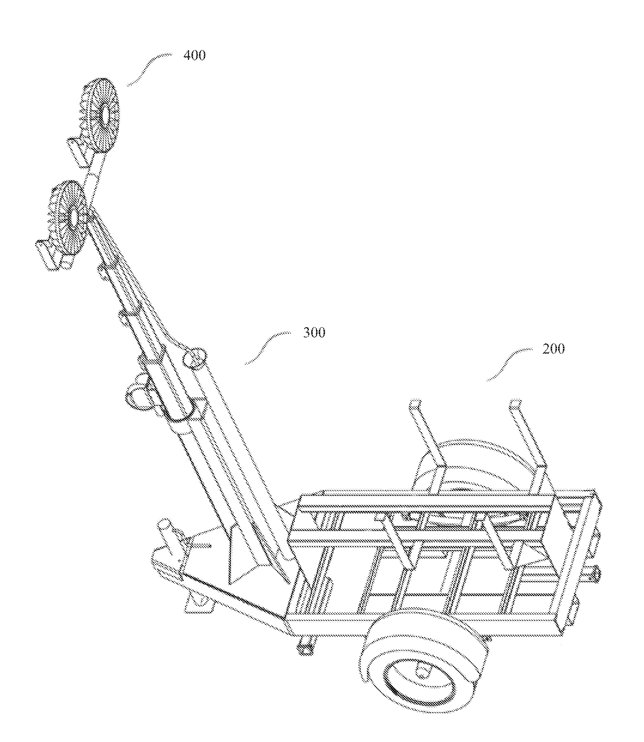
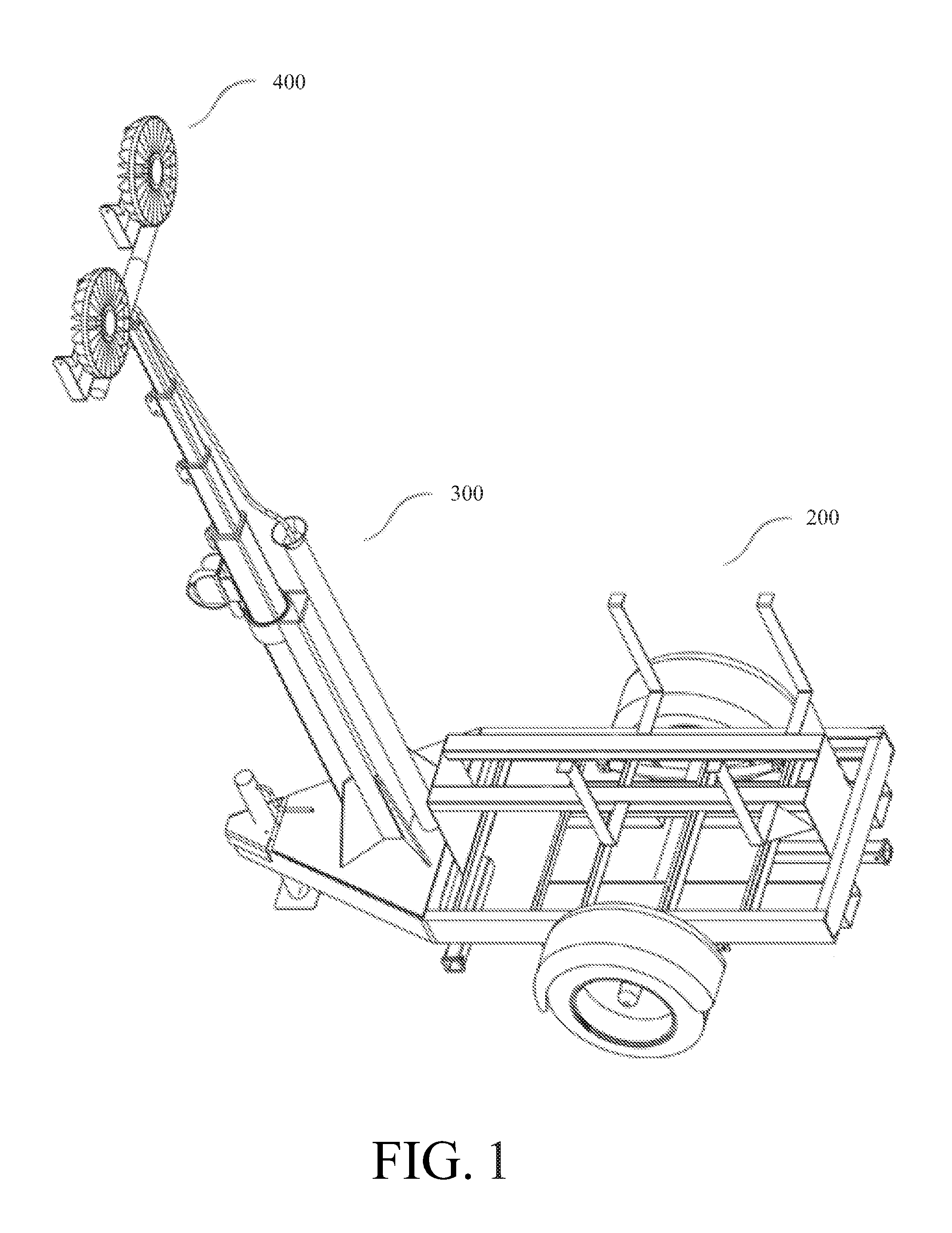
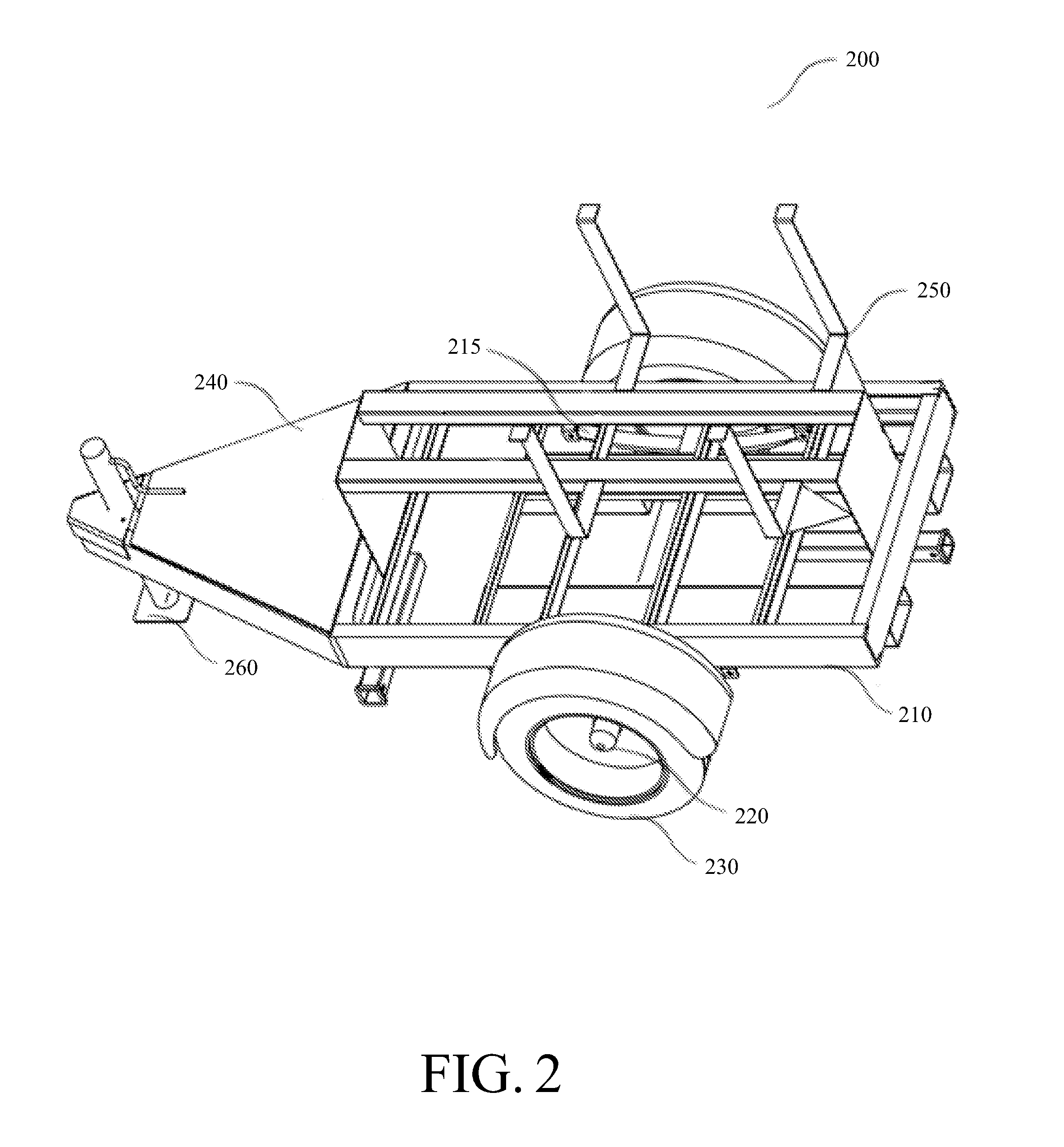
The patent describes a trailer frame component that includes a trailer, axle, wheels, hitch, and stand for supporting the frame when not being towed. The frame has a flat surface for mounting a mast component and a bed made of steel in a rectangular configuration with perimeter walls to contain any effluents from other components and protect the environment. The frame also has forklift receptacles on each side and is easy to load and unload from the side of a flatbed truck. The axle is designed to fit a 5.2 foot trailer width. The hitch is a standard pintle hitch for ease of towing. Additionally, an AC / DC power center is coupled between the charge controller and the battery, which includes various breakers and bypass switches to protect the system and prevent excessive current and power draw. The power center can also include an AC section to break the AC power from the inverter to the light component. The technical effects of the patent include the ability of the trailer frame component to safely and efficiently contain effluents from other components and protect the environment, as well as safely and easily load and unload from a flatbed truck. The power center ensures reliable and efficient power distribution to the light component.

Problems solved by technology

However, in some applications, temporary or emergency electrical power may be needed.
With the volatility of oil prices, diesel is, at times, very expensive, causing the cost of using the lights to increase substantially.
Tower lights are generally diesel powered, producing unwanted noise and pollution.
Solar powered tower lights tend to be unwieldy in terms of size and shape.
Light components are generally supported by masts which are folded horizontally flat on the structure component, a configuration which tends to damage the solar panels.

Method used


Image

  • Mobile Renewable Energy Light Tower
  • Mobile Renewable Energy Light Tower
  • Mobile Renewable Energy Light Tower

Examples


Embodiment Construction

[0062]Before the invention is described in further detail, it is to be understood that the invention is not limited to the particular embodiments described, as such may, of course, vary. It is also to be understood that the terminology used herein is for the purpose of describing particular embodiments only, and not intended to be limiting, since the scope of the present invention will be limited only by the appended claims.

[0063]Where a range of values is provided, it is understood that each intervening value, to the tenth of the unit of the lower limit unless the context clearly dictates otherwise, between the upper and lower limit of that range and any other stated or intervening value in that stated range is encompassed with the invention. The upper and lower limits of these smaller ranges may independently be included in the smaller ranges is also encompassed within the invention, subject to any specifically excluded limit in the stated range. Where the stated range includes on...


PUM


Abstract

The present invention is directed to a mobile light tower that utilizes multiple sources of energy to provide a highly energy efficient source of illumination. The components are mounted on a frame providing double wall containment. The electrical components are mounted on an interior component mount allowing the electrical subsystem to be assembled independently from the rest of the mobile light tower. Leg assemblies supporting the mobile light tower can be folded up flush into a channel in the mobile light tower housing.

Description

CROSS-REFERENCE TO RELATED APPLICATIONS[0001]The present application is a continuation-in-part, and claims the benefit, of U.S. patent application Ser. No. 14 / 601,982 filed on Jan. 21, 2015, which application claims priority to U.S. Provisional Application No. 61 / 933,326 filed on Jan. 30, 2014, both of which are incorporated by reference herein.FEDERALLY SPONSORED RESEARCH[0002]Not applicable.SEQUENCE LISTING OR PROGRAM[0003]Not applicable.FIELD OF INVENTION[0004]The present invention relates to the field of portable lighting systems and devices. More specifically, the invention is directed to the field of portable lighting systems and devices utilizing multiple sources of power.BACKGROUND OF THE INVENTION[0005]A solar power system uses one or more solar panels to convert sunlight into electricity. Solar power systems consist of multiple components, including the photovoltaic modules, mechanical and electrical connections and mountings and means of regulating or modifying the electr...

Claims


Application Information

Patent Timeline
Patent Type & Authority Applications(United States)
IPC IPC(8): F21L2/00F21L4/08H04N7/18F21V21/10F21V21/22F21V21/14F21L13/00F21L4/02
CPCF21L2/00F21L13/00F21L4/08H04N7/183F21V21/10F21V21/22F21V21/145F21L4/02F21S9/037F21S9/04F21W2131/10F21S9/043Y02B20/72F21L14/04
Inventor CARPOFF, JEFF
Owner CARPOFF JEFF
Learn More