
Optical demultiplexing apparatus and method for multi-carrier distribution

a multi-carrier, optical demultiplexing technology, applied in the field of optical demultiplexing apparatus and multi-carrier distribution, to achieve the effect of efficient demultiplexing of multi-carrier light sources

Inactive Publication Date: 2016-09-29
ELECTRONICS & TELECOMM RES INST
View PDF20 Cites 0 Cited by
  • Summary
  • Abstract
  • Description
  • Claims
  • Application Information

AI Technical Summary

Benefits of technology

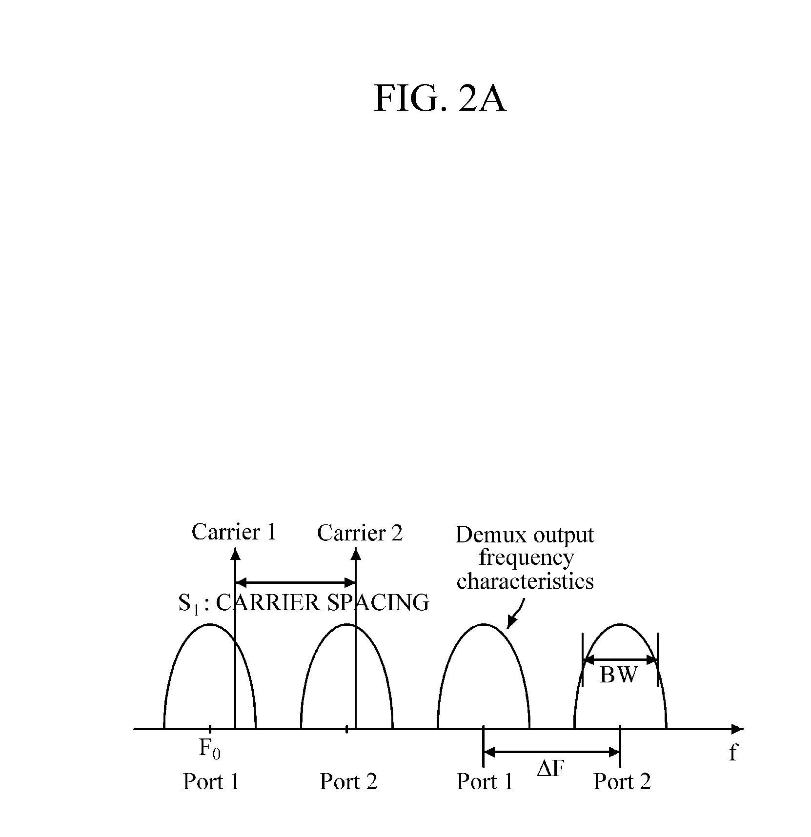
The patent describes a way to efficiently spread out light from a multi-carrier light source using a single optical device. This means that the spacing between the carriers can change, and the optical demultiplexer can still work effectively. The technical effect of this is that it enables more efficient and reliable use of multi-carrier light sources in optical networks.

Problems solved by technology

However, design and production of an optical demultiplexing apparatus whose channel spacing is tunable have been a challenge not only from technical and economical perspectives but also from a size perspective.

Method used


Image

  • Optical demultiplexing apparatus and method for multi-carrier distribution
  • Optical demultiplexing apparatus and method for multi-carrier distribution
  • Optical demultiplexing apparatus and method for multi-carrier distribution

Examples


Embodiment Construction

[0034]The following description is provided to assist the reader in gaining a comprehensive understanding of the methods, apparatuses, and / or systems described herein. Accordingly, various changes, modifications, and equivalents of the methods, apparatuses, and / or systems described herein will be suggested to those of ordinary skill in the art. Also, descriptions of well-known functions and constructions may be omitted for increased clarity and conciseness.

[0035]It will be understood that the terms “comprises” and / or “comprising,” when used in this specification, specify the presence of stated features, integers, steps, operations, elements, and / or components, but do not preclude the presence or addition of one or more other features, integers, steps, operations, elements, components, and / or groups thereof.

[0036]Hereinafter, an apparatus and method for distributing a multi-carrier light source by adjusting frequencies will be described with reference to the accompanying drawings.

[00...


PUM


Abstract

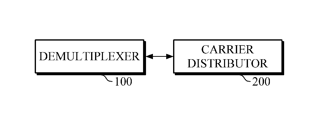
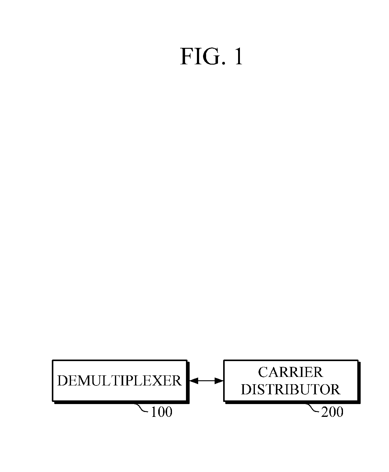
An optical demultiplexing apparatus and method for multi-carrier distribution are provided. The optical demultiplexing apparatus may include a demultiplexer and a carrier distributor. The optical demultiplexing apparatus and method allow efficient demultiplexing of a multi-carrier light source by using a single demultiplexer even when a carrier spacing of the light source varies.

Description

CROSS REFERENCE TO RELATED APPLICATION[0001]This application claims priority from Korean Patent Application No. 10-2015-0041726, filed on Mar. 25, 2015, in the Korean Intellectual Property Office, the disclosure of which is incorporated herein by reference in its entirety.BACKGROUND[0002]1. Field[0003]The following description relates to an optical demultiplexing apparatus and method for multi-carrier distribution, and more particularly, to an apparatus and method for effectively distributing multi-carrier optical signal used in an optical communication system.[0004]2. Description of Related Art[0005]In order to achieve advanced, flexible, and smart long-distance optical transmission networks, a multi-carrier light source technology is required in a flexible optical transceiver that flexibly adjusts transmission capacity, thereby allowing for efficient use, re-distribution and services of the transmission capacity.[0006]This is because frequency spacing of carriers of a multi-carrie...

Claims


Application Information

Patent Timeline
Patent Type & Authority Applications(United States)
IPC IPC(8): G02B6/293H04L25/14
CPCG02B6/2938H04L25/14H04J14/02G02B6/29316G02B6/29386H04J14/0307
Inventor HUH, JOON YOUNGCHANG, SUN HYOKCHUNG, HWAN SEOK
Owner ELECTRONICS & TELECOMM RES INST
Learn More