Projection-type image display device

a projection-type image and display device technology, applied in semiconductor devices, lighting and heating apparatus, instruments, etc., can solve the problems of reducing the luminescence property of light sources and the lifetime of light sources, and achieve the effects of reducing the cost of projection-type image display devices, reducing weight, and efficient cooling of light sources

Active Publication Date: 2007-12-06
SANYO ELECTRIC CO LTD
View PDF5 Cites 8 Cited by
  • Summary
  • Abstract
  • Description
  • Claims
  • Application Information

AI Technical Summary

Benefits of technology

[0009] According to the aforementioned aspect, it is possible to frilly cool the light source for each color such as an LED and a laser element.
[0010] In the aforementioned aspect of the present invention, it is preferable that the third light source has the smallest calorific value of the three light sources. In this aspect, the third light source having the smallest calorific value of at least three light sources and the second light source are cooled by the same second cooler and therefore it is possible to cool the light sources efficiently.
[0011] In the aforementioned aspect of the present invention, the projection-type image display device further includes: a first optical path configured to guide a first outgoing light emitted from the first light source to the light combining unit; a second optical path configured to guide a second outgoing light emitted from the second light source to the light combining unit; and a third optical path configured to guide a third outgoing light emitted from the third light source to the light combining unit. In addition, it is preferable that the second optical path has a curve portion configured to fold the second outgoing light. According to the aforementioned aspect, the provision of the curve portion in the second optical path makes it possible to arrange the second and the third light source dose to each other and miniaturize the second cooler that cools the second and the third light source. Therefore, according to this projection-type image display device, it is possible to achieve miniaturization, reduction in weight, and reduction in the cost of the projection-type image display device.
[0012] In the aforementioned aspect of the present invention, it is preferable that each optical path has an integrator configured to uniformize an illumination distribution of the outgoing light emitted from respective light source. According to the aforementioned aspect, the provision of the integrator such as the rod integrator in the optical path makes it possible to provide a projection-type image display device that is capable of displaying a beautiful image with less irregularity in luminance or color. Moreover, the use of a reflector such as a triangular prism in the curve portion makes it possible to achieve an optical path with the curve portion in a simple structure.
[0013] In the aforementioned aspect of the present invention, it is preferable that respective cooler is a liquid cooler circulating a liquid coolant. Furthermore, it is preferable that respective cooler includes a Peltier device. Specifically, the cooler is a liquid cooler having a heat conduction unit, a radiator, and a coolant pipe. The heat conduction unit absorbs heat from the light source and conducts the resultant to the coolant. The radiator cools the coolant and radiates the resultant to the outside of the projection-type image display device. Then, the coolant pipe connects the heat conduction unit to the radiator in such a way to circulate the liquid coolant such as cooling water or oil, thereby making it possible to improve cooling ability of the cooler. Particularly, a heat transferable member such as a Peltier device is provided in the vicinity of the light source, thereby allowing heat to be forcibly absorbed from the light source, which makes it possible to cool the light source in a short period of time.
[0014] In the aforementioned aspect of the present invention, it is preferable that respective cooler includes a laser element. The use of a laser element as the light source for the projection-type image display device is useful from the viewpoint of laser properties (coherence level and luminous efficiency). On the other hand, there is a problem of a change in luminescence properties, which is called a rollover, due to environmental temperature, specifically, a reduction of the luminescence properties with an increase of the environmental temperature. Accordingly, the provision of the cooler as in the present invention allows the projection-type image display device to be operated efficiently.

Problems solved by technology

However, there has been a drawback that heat generated by the light source with high luminance causes a reduction in the luminescence property of the light source and a decrease in the lifetime thereof.

Method used


Image

  • Projection-type image display device
  • Projection-type image display device
  • Projection-type image display device

Examples


Embodiment Construction

[0019] Hereinafter, explanation will be given for a projection-type image display device of the present invention.

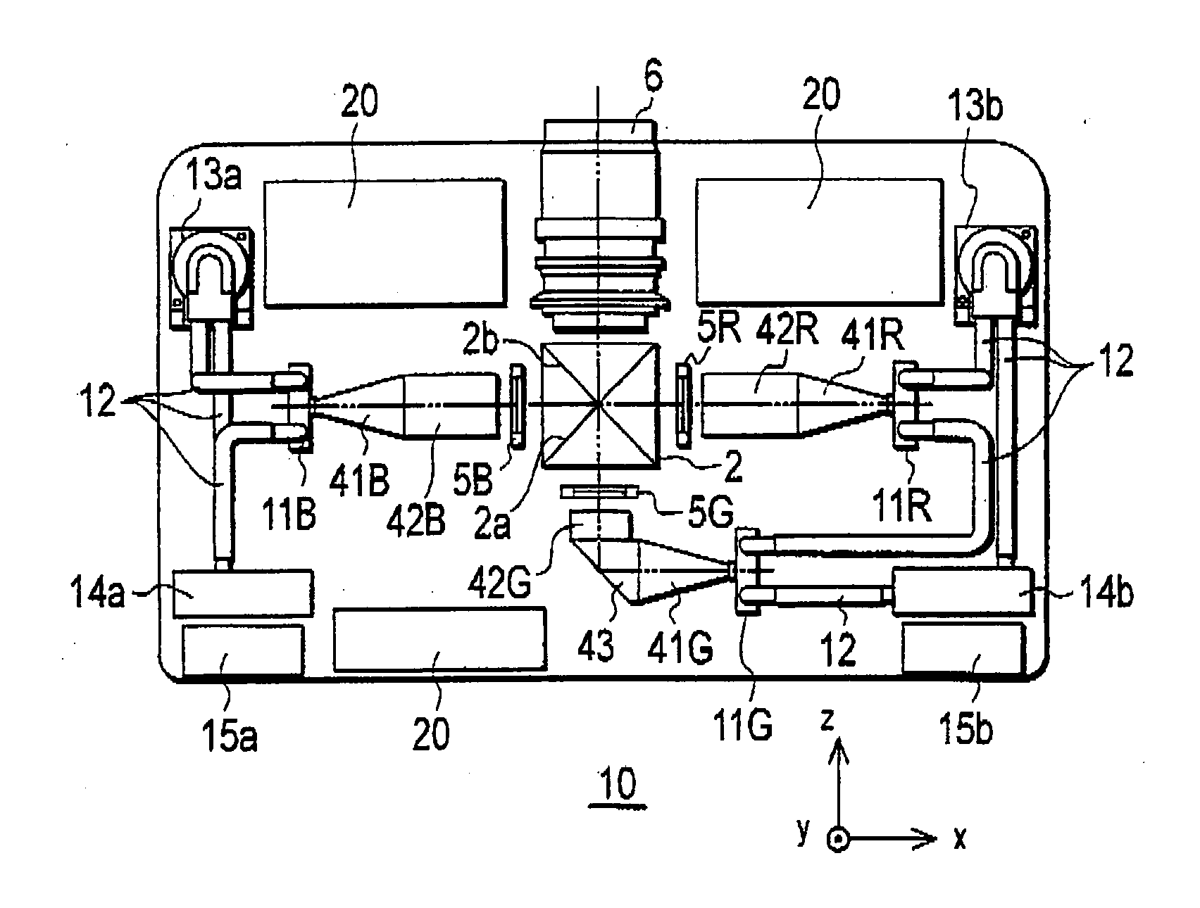
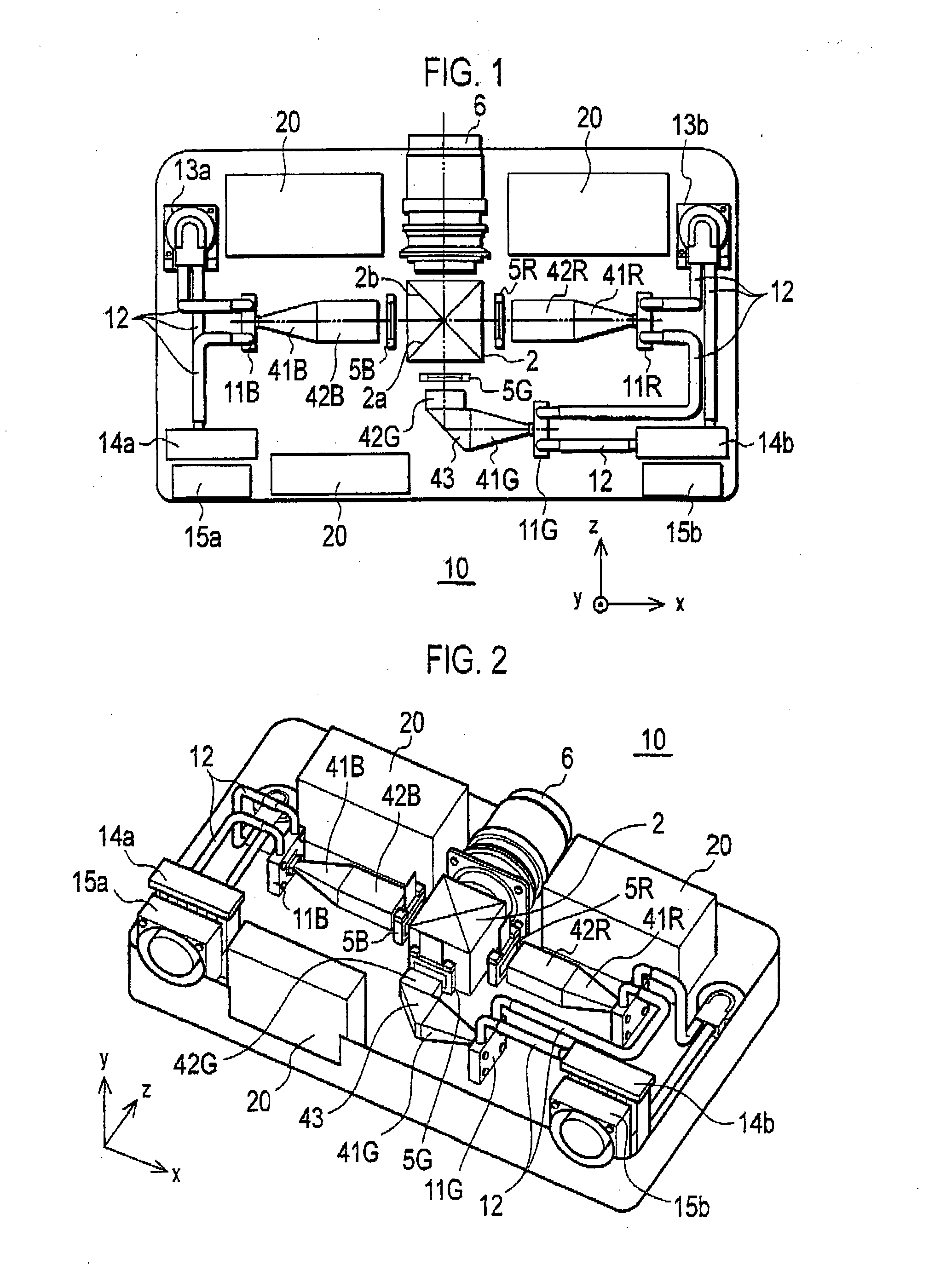
[0020]FIGS. 1 and 2 are views each illustrating the structure of a projection-type image display device 10. FIG. 1 is a plan view and FIG. 2 is a perspective view. The projection-type image display device 10 includes, in its housing, a plurality of light sources 11 (11R 11G, 11B), a plurality of first rod integrators 41 (41R, 41G, 41B), a plurality of second rod integrators 42 (42R, 42G, 421), a triangular prism 43, a plurality of liquid crystal panels 5 (5R, 50, 5B), a dichroic prism 2, a projection lens 6, pipes 12, a plurality of radiators 14 (14a, 14b), and a plurality of blower fans 15 (15a, 15b). Moreover, in the same figure, reference numeral 20 indicates an electrical circuit 20.

[0021] (Explanation of Optical System of Projection-Type Image Display Device 10)

[0022] An optical system of the projection-type image display device 10 will be first explained. The li...


PUM


Abstract

A projection-type image display device includes three light sources respectively configured to emit a different colored outgoing light, a light combining unit configured to combine outgoing lights, and a projection unit configured to project a combined light combined by the light combining it. The projection-type image display device includes a first cooler configured to cool a first light source of the three light sources, and a second cooler configured to cool a second and a third light source of the three light sources except the first light source.

Description

CROSS REFERENCE TO RELATED APPLICATIONS [0001] This application is based upon and claims the benefit of priority from prior Japanese Patent Application No. 2006-124534, filed on Apr. 27, 2006; and Japanese Patent Application No. 2007-115474, filed on Apr. 25, 2007; the entire contents of which are incorporated herein by reference. BACKGROUND OF THE INVENTION [0002] 1. Field of the Invention [0003] The present invention relates to a projection-type image display device including units for cooling light sources. [0004] 2. Description of the Related Art [0005] A projection-type image display device uses a halogen lamp as a light source, and is configured to modulate lights emitted from the light source using a light valve such as a liquid crystal panel and configured to project the resultant light. Accordingly, a projection-type image display device needs to have a light source with high luminance. However, there has been a drawback that heat generated by the light source with high lum...

Claims


Application Information

Patent Timeline
Patent Type & Authority Applications(United States)
IPC IPC(8): F21V29/00F21V8/00
CPCF21V29/30F21Y2101/02H04N9/315H04N9/3144G03B21/16F21Y2115/10F21V29/56F21V29/54
Inventor MIWA, TAKASHIARAI, KAZUHIROYOKOTE, YOSHIHIRO
Owner SANYO ELECTRIC CO LTD
Why Eureka
Try Eureka