Flexible cold plate with enhanced flexibility

Inactive Publication Date: 2016-10-06
IBM CORP
View PDF13 Cites 32 Cited by
  • Summary
  • Abstract
  • Description
  • Claims
  • Application Information

AI Technical Summary

Benefits of technology

[0014]There is provided a practical design for a heat sink or cooling plate cooling device that implements a reduced the heat sink height between active areas to reduce the stiffness of the heat sink sidewall.
[0015]Generally, in one aspect, the height of the sidewalls (and generally the height of the cold plate) is reduced between the active areas in order to improve flexibility. The stiffness of the sidewalls is an exponential function of their height, making it very advantageous to reduce the height.
[0016]In one aspect, the sidewalls are shorter than the active area height only between active areas. Alternately, there is a reduced sidewall height everywhere by insetting the active areas within the top and/or bottom sheets.
[0017]According to an aspect of the present disclosure, there is provided a cooling apparatus for an electronic device.

Problems solved by technology

When the height difference increases and the active area is near the allowed width of the flexible heat sink, such features are less effective.
Such features also complicate flow control/blocking outside the activ

Method used


Image

  • Flexible cold plate with enhanced flexibility
  • Flexible cold plate with enhanced flexibility
  • Flexible cold plate with enhanced flexibility

Examples


first embodiment

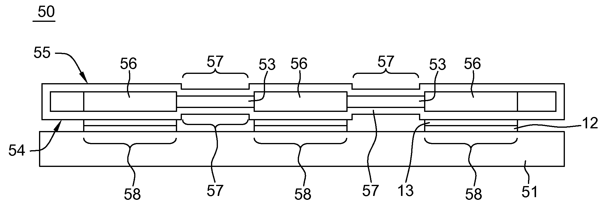
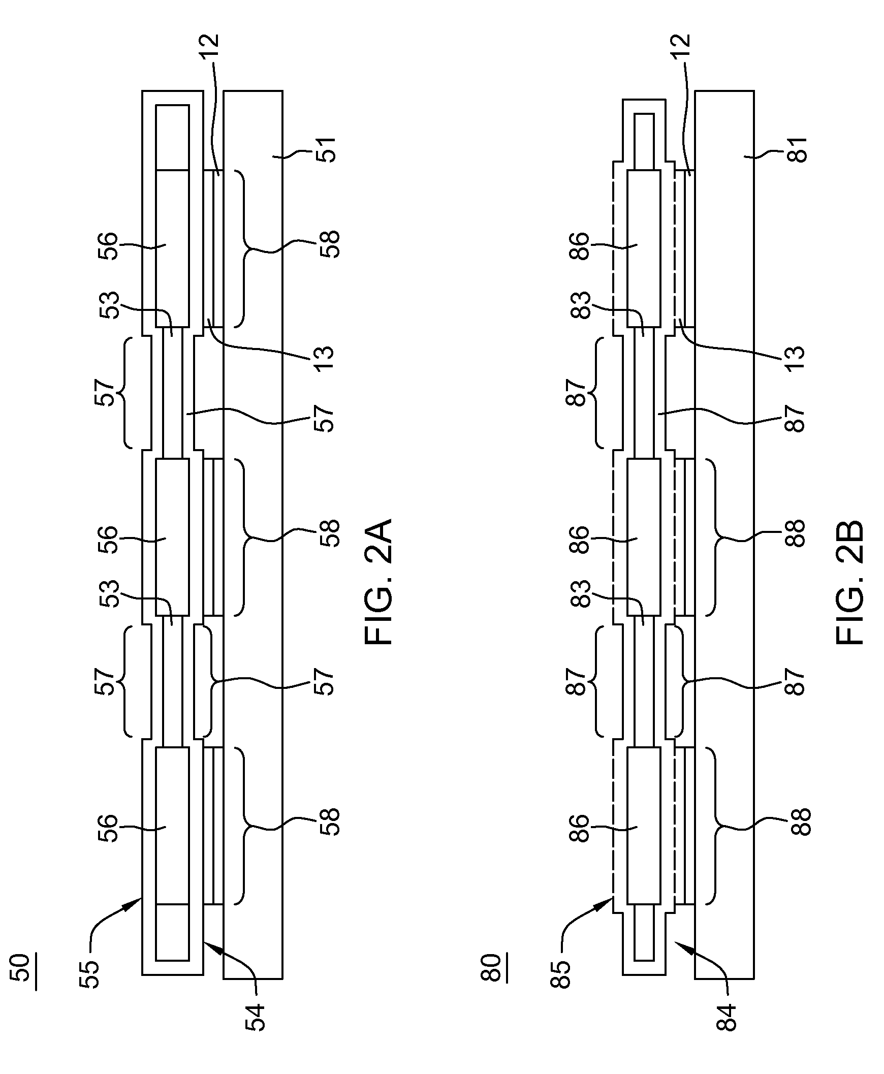
[0037]FIG. 2A shows conceptually the heat sink or cold plate design 50 (a “cooling apparatus”) of enhanced flexibility that incorporates reduced height wall features that reduce stiffness of the wall structure according to a In the embodiment of FIG. 2A, the side wall 57 joining parallel top sheet 55 and bottom sheet 54 comprises a reduced height feature structured intermittent about the periphery to surround active regions, i.e., the wall 57 is shorter than the active area height only between active area locations 58 of the heat sink (or cold plate) corresponding to those areas that provide an interface for heat exchange between the chip 12 (or chip module), and the apparatus and correspond to locations where heat transfer elements (HTE) 56 such as fins, pins or other heat transfer structures are mounted between flexible heat sink sheets 54, 55. That is, as shown in FIG. 2A, the heat sink 50 with enhanced flexibility is shown mated with or secured in heat exchange relation with el...

embodiment 50

[0039]FIG. 3 shows an exposed perspective cross-sectional view of a heat sink cooling device 60 according to one embodiment of the present disclosure. This embodiment corresponds to the cooling apparatus embodiment 50 of FIG. 2A. In the embodiment depicted in FIG. 3, the heat sink cooling apparatus 60 includes joined, parallel formed members including a top thin-walled sheet (or plate) member 64, and a bottom thin-walled plate member 65 that form an enclosed space or chamber for air or fluid flow therein. In this embodiment of a cooling device, each top and bottom members 64, 65 include respective sidewall portions 64A, 65A of a first height and respective sidewall portions 65A, 65B of a second height where the top and bottom members 64, 65 are brazed or soldered together to form an enclosed space therebetween. The height of the sidewall portions 64A, 65A of a first height is sufficient for accommodating cooling structures 66 mounted therebetween. The second height 67 of the joined ...


PUM


Abstract

An apparatus for cooling an electronic component has a planar top member of a thermal energy conductive material and a parallel planar bottom member of the material, the planar bottom member including a surface having regions configured for heat exchange contact with the electronic component. The joined planar top and bottom members have a sidewall structure of reduced height (and generally the height of the cold plate) between active areas in order to improve flexibility. The stiffness of the sidewalls is reduced by very advantageously reduce the height of the sidewalls. In one embodiment, the sidewalls are shorter in height corresponding to regions only between active areas. Alternatively, the sidewalls are of reduced height everywhere by insetting the active areas within the top and/or bottom sheets.

Description

CROSS-REFERENCE TO RELATED APPLICATIONS[0001]The present disclosure is a conversion application of U.S. Patent Application Ser. No. 62 / 143,612, the contents of which are wholly incorporated herein.STATEMENT REGARDING FEDERALLY SPONSORED RESEARCH / DEVELOPMENT[0002]This invention was made with Government support under Contract Numbers: B601996 and B604142 awarded by Department of Energy. The Government has certain rights in this invention.FIELD[0003]The present disclosure generally relates to heat sinks, such as used for cooling components in electronic devices, e.g., computers, and more particularly to a flexible thin-walled cooling apparatus (heat sink or cold plate).BACKGROUND[0004]With the increase in heat dissipation from microelectronic devices and the reduction in overall form factors, thermal management becomes a more and more important element of electronic product design. Both the performance reliability and life expectancy of electronic equipment are inversely related to the...

Claims


Application Information

Patent Timeline
IPC IPC(8): F28D1/03F28F3/06H05K7/20
CPCF28D1/0358F28F3/06H05K7/20509F28F3/044F28F3/12F28F2225/04F28F2255/02H01L23/473H05K7/20254
Inventor COTEUS, PAUL W.HALL, SHAWN A.SCHULTZ, MARK D.TAKKEN, TODD E.TIAN, SHURONG
Owner IBM CORP
Why Eureka
Try Eureka