Method of conducting probe coupling calibration in a guided-wave inspection instrument

a technology of guided wave inspection and coupling calibration, which is applied in the direction of instruments, scientific instruments, measurement devices, etc., can solve the problems of non-uniform coupling between the transducer and the elongated structure of such inspection instruments, and the method is not used for the calibration of guided wave inspection instruments. achieve the effect of uniform sensitivity, ensure the repeatability of the measured modes associated, and improve the capacity of the guided wave inspection instrumen

Active Publication Date: 2016-10-06
OLYMPUS AMERICA
View PDF4 Cites 10 Cited by
  • Summary
  • Abstract
  • Description
  • Claims
  • Application Information

AI Technical Summary

Benefits of technology

[0015]The benefits of having uniform sensitivity over the circumference of the pipe are found on at least two main levels. On a first level, the received signals may now be expanded in normal modes with minimal coupling bias, thus improving the capacity of the guided wave inspection instrument to localize structural defects. Carrying out the calibration procedure for every new mechanical installation of the guided wave inspection instrument ensures the repeatability of the measured modes associated with a given reflector. On a second level, the transmitted signals may now be better controlled, thus enabling repeatable advanced “focus” forming techniques (such as the one presented in U.S. Pat. No. 7,997,139 B2) with dry coupled transducers.
[0016]Furthermore, the improved modal discrimination at the emission level can lead to a more energy efficient instrument because losses associated with the excitation of non-propagating modes otherwise unwillingly transmitted in the pipe by lack of knowledge of the coupling coefficients may now be minimized.

Problems solved by technology

However, the coupling between the transducers of such inspection instruments and the elongated structure is often non-uniform.
However, this method is not used for the calibration of the guided wave inspection instrument since the beam is formed of free propagating wave packets.

Method used


Image

  • Method of conducting probe coupling calibration in a guided-wave inspection instrument
  • Method of conducting probe coupling calibration in a guided-wave inspection instrument
  • Method of conducting probe coupling calibration in a guided-wave inspection instrument

Examples


Embodiment Construction

[0031]This section provides further details on the invention, with reference to the drawing boards above.

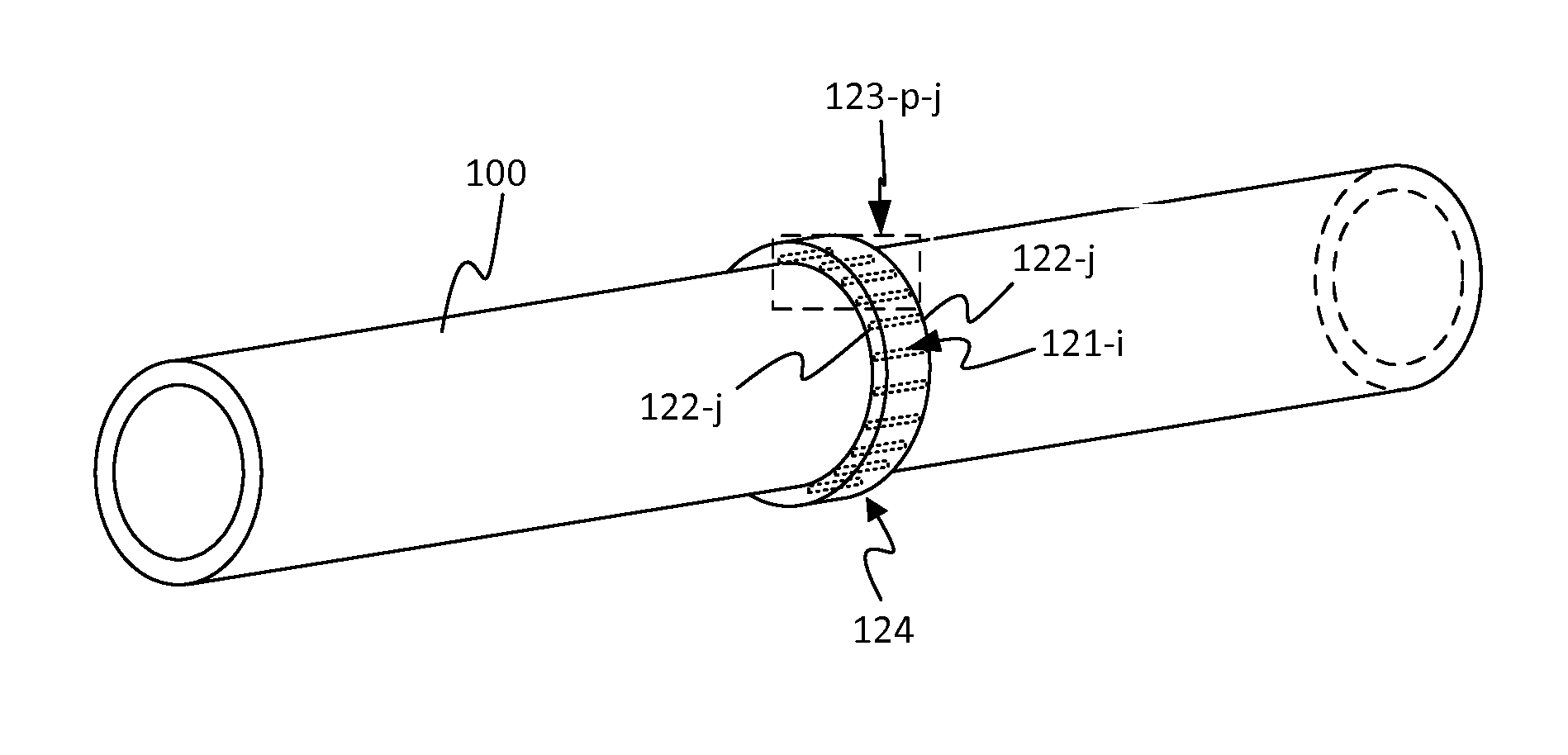
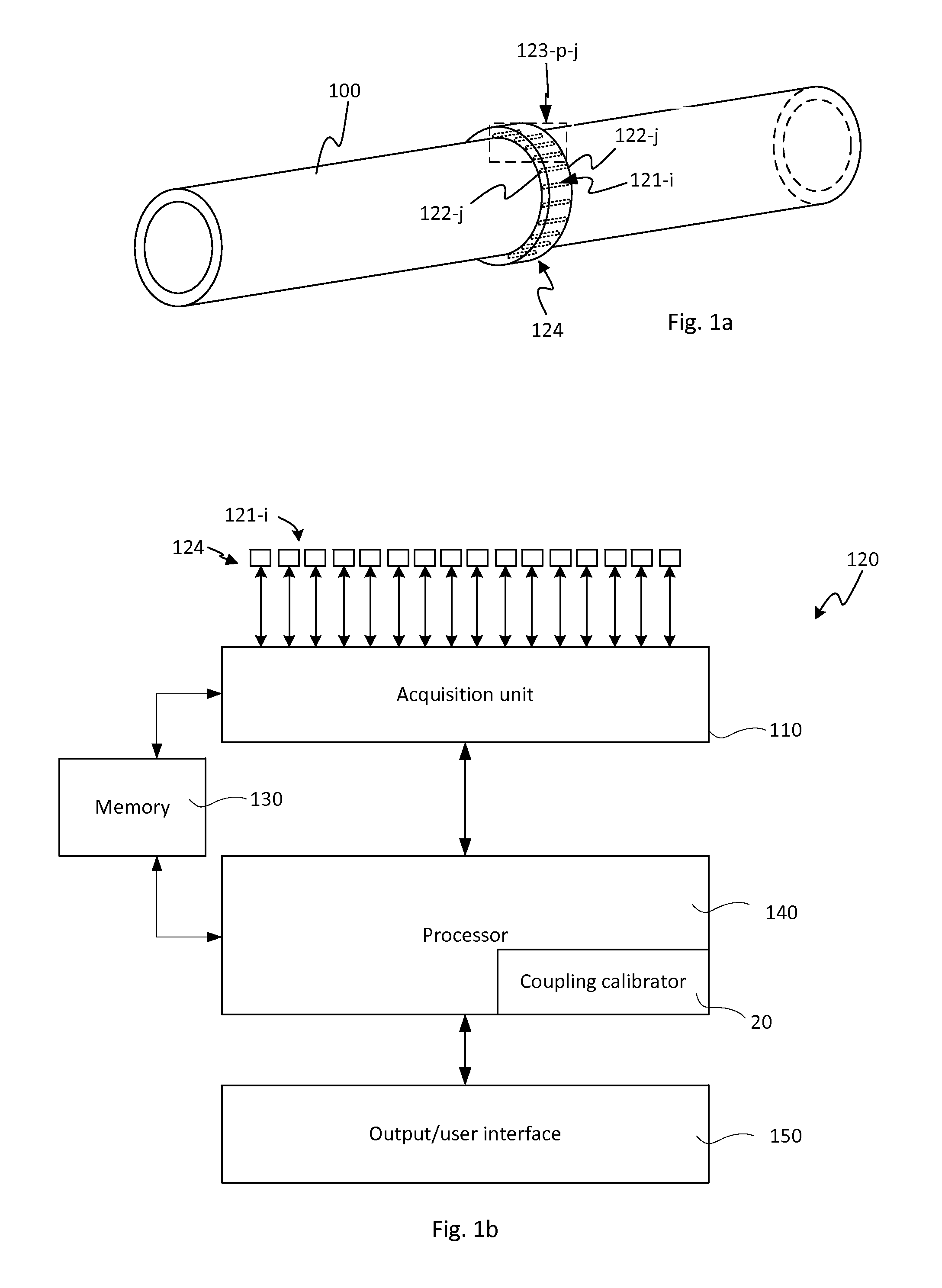
[0032]The current invention applies to the calibration of a guided wave inspection instrument 120 comprising a probe assembly 124 with regards to its acoustic coupling with an elongated test object in which a guided wave can propagate. The elongated test object to be inspected typically has a test surface, typically provided in the form of a circular cross-section, on at least a portion of the elongated test object. For instance, the elongated test object may have a cylindrical shape which may or may not be constant along its length. In an embodiment, the elongated test object may have elbows or shoulders at some positions along its length.

[0033]FIG. 1a shows the physical appearance of the guided wave probe assembly 124 properly installed on a section of an elongated test object 100. The probe assembly 124 comprises acoustic transducers 122-j for transmitting acoustic energy alon...


PUM

PropertyMeasurementUnit
period of timeaaaaaaaaaa
driving voltagesaaaaaaaaaa
central frequenciesaaaaaaaaaa

Abstract

The method for calibrating an inspection instrument coupled with acoustic transducers disposed at circumferential positions distributed around a surface of an elongated object to inspect generally has the steps of: for each one of the circumferential positions, measuring a first and a second received signal using two acoustic transducers disposed at two axial positions along the object, the received signals resulting from the propagation of an acoustic guided wave signal along the object; identifying an acoustic mode according to the first received and the second received signals using a known period of time associated with the propagation of the acoustic guided wave signal between the two axial positions along the object; and determining a coupling coefficient associated with the acoustic mode, the coupling coefficient being indicative of the coupling of the acoustic transducers on the object; and calibrating the inspection instrument coupled to the object based on the coupling coefficients.

Description

FIELD OF THE INVENTION[0001]This invention relates to the calibration of long range non-destructive testing and inspection systems (NDT / NDI) using acoustic guided modes propagating in elongated test objects. This invention is especially concerned with the calibration of portable guided wave inspection instruments that, when coupled with the elongated test object, relay acoustic waves from the transducer to the test object, and conversely from the test object to the transducer.BACKGROUND OF THE INVENTION[0002]The use of acoustic guided waves is a promising way to screen corrosion and general wall thinning in elongated test objects such as pipelines. The capacity to assess structural integrity several meters at a time in an elongated structure offers opportunities to decrease inspection costs by pinpointing specific areas of concern. Acoustic guided waves enable a more thorough evaluation of structures with respect to conventional NDT / NDI means spot checks based on historical knowledg...

Claims


Application Information

Patent Timeline
Patent Type & Authority Applications(United States)
IPC IPC(8): G01N29/30G01N29/28G01N29/07
CPCG01N29/30G01N2291/262G01N29/28G01N29/07G01N29/226G01N2291/0425G01N2291/2634
Inventor LEPAGE, BENOITPAINCHAUD-APRIL, GUILLAUME
Owner OLYMPUS AMERICA
Why Eureka
Try Eureka