Coil component

a technology of components and coils, applied in the direction of transformer/inductance magnetic cores, inductances with magnetic cores, inductances, etc., can solve the problems of limiting the pressure that can be applied, insulation properties falling, etc., and achieves superior saturation characteristics and high packing.

Active Publication Date: 2016-10-06
TAIYO YUDEN KK
View PDF3 Cites 6 Cited by
  • Summary
  • Abstract
  • Description
  • Claims
  • Application Information

AI Technical Summary

Benefits of technology

[0007]For a laminated inductor, etc., a powder compact achieving higher packing and superior saturation characteristics than heretofore achievable is desired. However, a manufacturing process that involves layering of green sheets, etc., for example,

Problems solved by technology

However, a manufacturing process that involves layering of green sheets, etc., for example, limits the pressures that

Method used


Image

  • Coil component
  • Coil component

Examples


examples

[0063]The present invention is explained in greater detail below using examples. It should be noted, however, that the present invention is not limited in any way to the modes described in these examples.

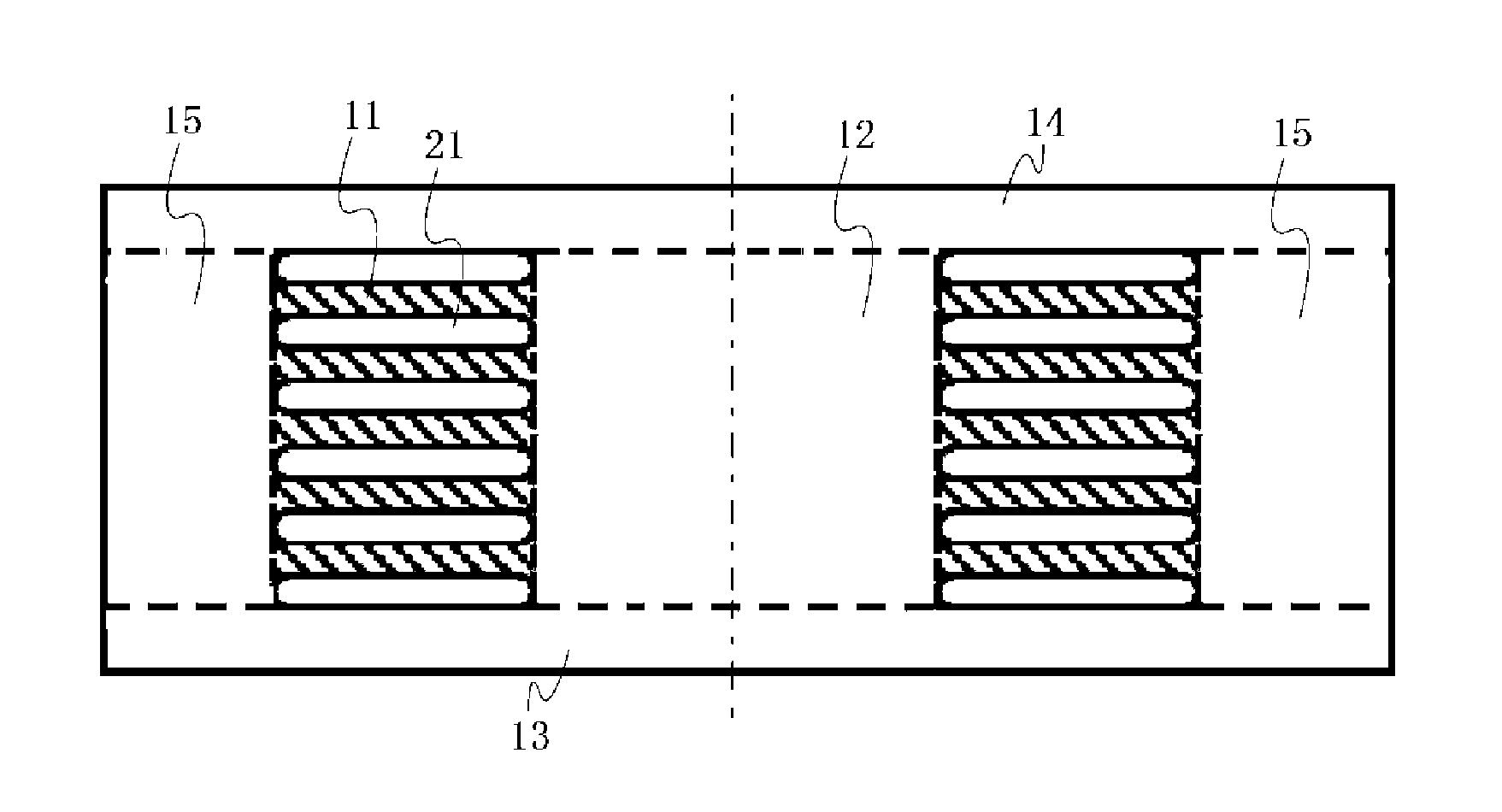
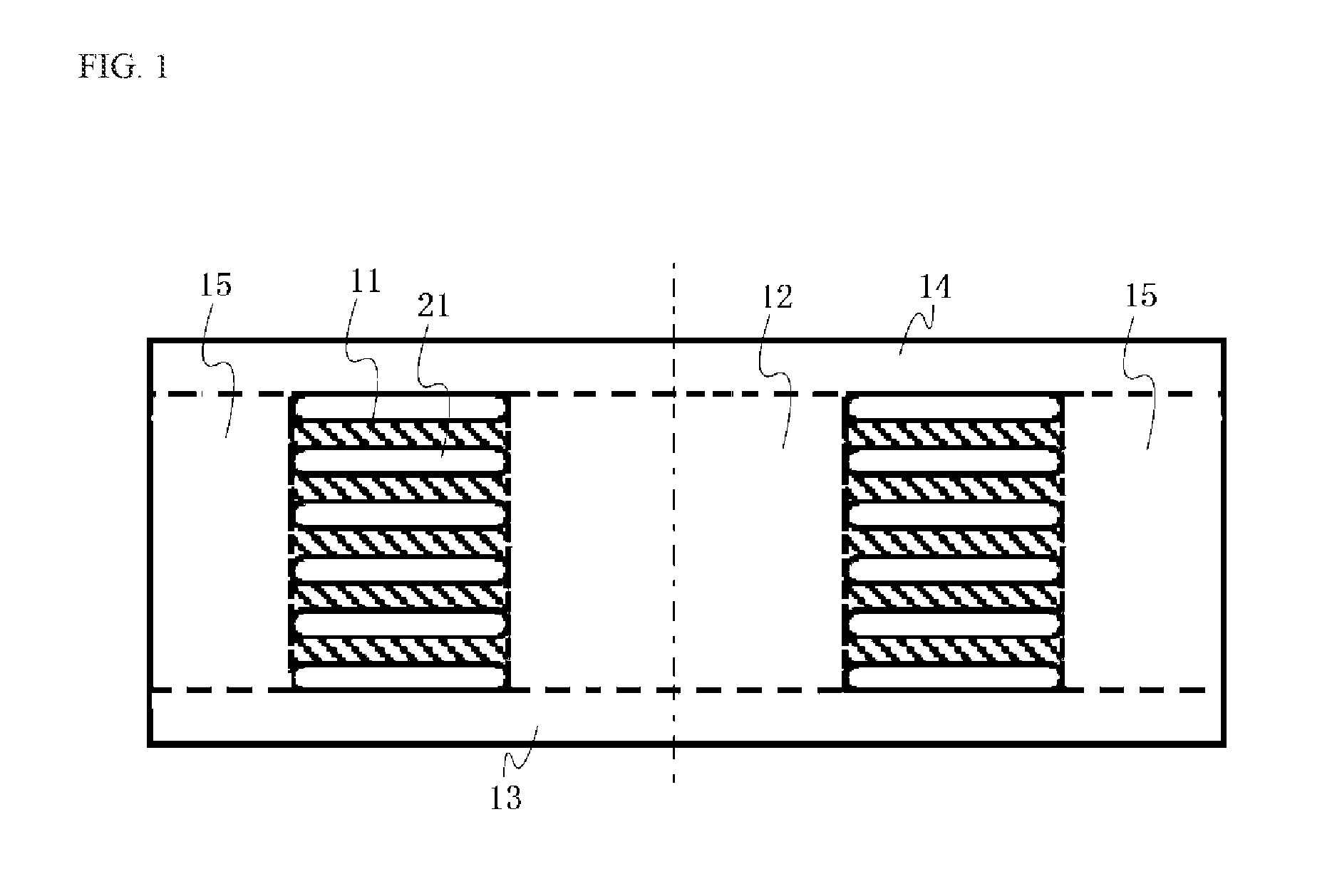
[0064]A laminated inductor was manufactured as described below. This is explained based on the schematic cross sectional view of the laminated inductor shown in FIG. 1.

[0065]For the respective magnetic bodies, the material grains listed in Table 1 were used. The material grains in the table were as follows: the FeSiCr (1) grain had a composition of Si by 3.5 percent by weight, Cr by 4.0 percent by weight, and Fe accounting for the rest, as well as an average grain size of 6 um; the FeSiCr (2) grain had a composition of Si by 2.0 percent by weight, Cr by 2.0 percent by weight, and Fe accounting for the rest, as well as an average grain size of 6 um; the FeSiAl grain had a composition of Si by 3.5 percent by weight, Al by 4.0 percent by weight, and Fe accounting for the rest, as well ...


PUM


Abstract

In an embodiment, a coil component includes a magnetic body, and an internal conductor 21 having a center axis and formed in a spiral shape; wherein the internal conductor 21 is embedded in the magnetic body; in a cross sectional view of a plane that includes the center axis extending in the vertical direction, wherein a conductor region part 11 positioned between the adjacent windings of the spiral shape has a higher oxygen content than that of a core part 12 including the center axis and positioned on the inner side of the windings of the spiral shape. the magnetic body is constituted by iron-based soft magnetic grains and oxide film of at least one type of element that oxidizes more easily than iron, which oxide film bonds at least partly the iron-based soft magnetic grains.

Description

BACKGROUND[0001]1. Field of the Invention[0002]The present invention relates to a coil component, one representative example of which is a laminated inductor.[0003]2. Description of the Related Art[0004]Inductor components are increasingly designed with higher current ratings while facing a demand for supporting higher frequencies in recent years. To respond to the call for higher current ratings, switching materials from ferrite materials to metal materials such as Fe and alloys is being studied. When these metal materials are used, a conventional approach has been to bond magnetic grains using resin or glass or sinter the magnetic grains together. If resin is used, however, more resin must be added to ensure strength and consequently the packing ratio of magnetic grains drops and sufficient magnetic permeability cannot be achieved. On the other hand, sintering achieves high magnetic permeability, but it puts limitations in terms of frequencies due to the effect of loss, which in t...

Claims


Application Information

Patent Timeline
IPC IPC(8): H01F27/28H01F1/14H01F27/255
CPCH01F27/2804H01F2027/2809H01F1/14H01F27/255H01F17/0006H01F17/0013H01F27/25H01F17/04H01F2017/0073H01F2017/048H01F41/0246
Inventor TAKEOKA, SHINSUKEYAMAGUCHI, AKIKOOTAKE, KENJI
Owner TAIYO YUDEN KK
Why Eureka
Try Eureka