
Charger, charging system and power tool with battery pack

a charging system and power tool technology, applied in the direction of electric vehicles, transportation and packaging, and battery pack arrangements, etc., can solve the problems of battery pack temperature rising quickly, battery pack cooling process generally requires a long time, and the battery pack cannot be quickly charged

Active Publication Date: 2016-10-06
CHERVON HK LTD WANCHAI
View PDF6 Cites 9 Cited by
  • Summary
  • Abstract
  • Description
  • Claims
  • Application Information

AI Technical Summary

Benefits of technology

The patent is about a system that prevents batteries from overheating and slows down the charging process to prevent damage. While this system prevents the battery from being charged when it is too hot, it can also cause the battery to cool too slowly. This can make the battery unusable for a long period of time, and may even decrease its lifespan. Therefore, there is a need to improve the cooling process to allow batteries to charge quickly without causing damage.

Problems solved by technology

However, the cooling process generally requires a long time, and the battery pack cannot be charged quickly.
Further, during the discharging process, the temperature of the battery pack may rise quickly, and the high temperature may reduce the useful life of the battery pack.

Method used


Image

  • Charger, charging system and power tool with battery pack
  • Charger, charging system and power tool with battery pack
  • Charger, charging system and power tool with battery pack

Examples


Embodiment Construction

[0019]The following description of embodiments is merely exemplary in nature and is in no way intended to limit the scope of the invention hereinafter claimed, its application, or uses.

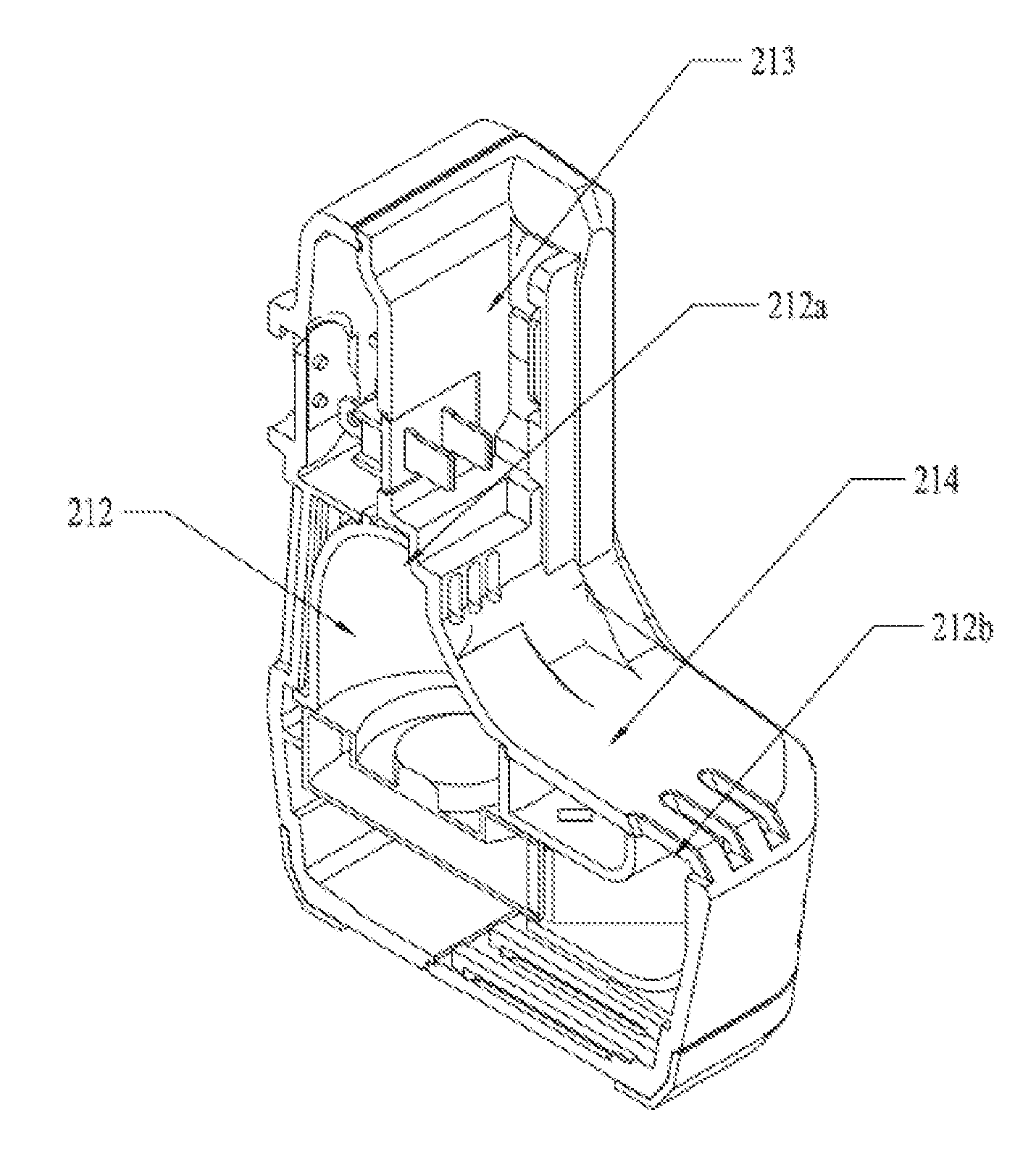
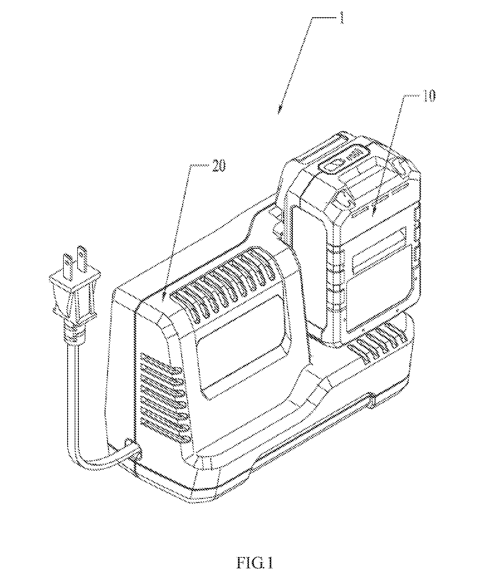
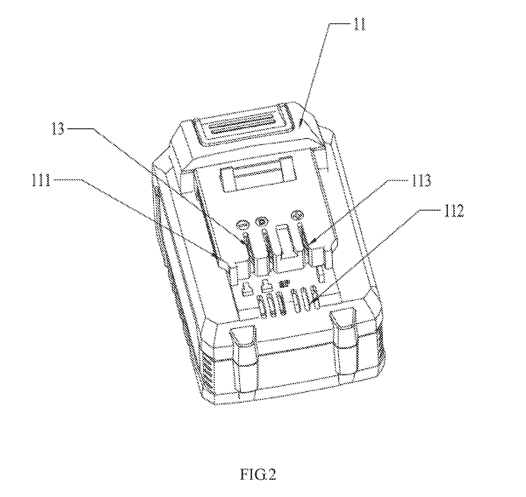
[0020]Referring to FIGS. 1-6, an electrical combination 1 includes a battery pack 10 and a charger 20. The battery pack 10 includes a battery pack housing 11 and battery cells 12. The charger 20 includes a charger housing 21 and a fan 22. The battery pack housing 11 includes a first connecting portion 111 for connecting the battery pack 10 to the charger 20. The battery pack housing 11 further includes a vent 112 for placing an inside and an outside of the battery pack housing 11 into fluid communication. The battery cells 12 are disposed within the battery pack housing 11 for storing electric power. The charger housing 21 includes a second connecting portion 211 for engaging with the first connecting portion 111. When the battery pack 10 is connected to the charger 20 through the engagement between t...


PUM


Abstract

A electrical combination includes a battery pack and a charger. The battery pack includes a battery pack housing including a first connecting portion for connecting the battery pack to the charger and a vent for placing an inside and an outside of the battery pack housing into communication. Battery cells are disposed within the battery pack housing. The charger includes a charger housing including a second connecting portion for engaging with the first connecting portion and an air flue having an air inlet and an air outlet, and a fan disposed within the charger housing. When the battery pack is connected to the charger, the air inlet is connected with the vent of the battery pack and the battery pack is positioned between the air outlet and the second connecting portion.

Description

RELATED APPLICATION INFORMATION[0001]This application claims the benefit under 35 U.S.C. §119(a) of Chinese Patent Application No. CN 201510145179.4, filed on Mar. 30, 2015, the disclosure of which is incorporated herein by reference in its entirety.FIELD OF THE DISCLOSURE[0002]The present disclosure relates generally to charging devices and, more particularly, to a charger, a charging system and a power tool with a battery pack.BACKGROUND OF THE DISCLOSURE[0003]High-powered chargers and battery packs have an over-temperature prevention system. With this over-temperature prevention system, the battery pack cannot be charged by the charger when the temperature of the battery cells is greater than a preset value. So the battery pack must be cooled. When the temperature of the battery pack is decreased to less than or equal to the present value, it can be charged. However, the cooling process generally requires a long time, and the battery pack cannot be charged quickly. Further, durin...

Claims


Application Information

Patent Timeline
Patent Type & Authority Applications(United States)
IPC IPC(8): H02J7/00
CPCH02J7/0013H02J7/0045H02J7/0042
Inventor TENG, ZHIHAIZHANG, YUEXIANG
Owner CHERVON HK LTD WANCHAI
Learn More