Devices and methods for parameter measurement

a technology of parameter measurement and device, applied in the field of device and method for parameter measurement, can solve the problems of diaphragm based sensors, rigidity and biocompatibility of silicon based sensors, limiting factors in thickness, etc., and achieve the effect of restoring vision

Inactive Publication Date: 2016-10-20
BOARD OF RGT THE UNIV OF TEXAS SYST
View PDF24 Cites 30 Cited by
  • Summary
  • Abstract
  • Description
  • Claims
  • Application Information

AI Technical Summary

Benefits of technology

[0072]If the sensor is configured as an array of frequency specific optical transducers, an optical camera can be achieved for imaging applications. A specific biomedical application of such an optical camera includes a retinal implant for restoring vision. The thin, flexible nature of the sensor confers a particular advantage for conforming to the curved topography of the eye.

Problems solved by technology

While these thick substrates confer stability during fabrication and over the long term, the thickness limits applications in tight spaces, which includes many biomedical and industrial conditions.
The rigidity and biocompatibility of silicon based sensors are additional limiting factors.
Overcoming these issues is particularly challenging for diaphragm based sensors, due to the tight control required to build three-dimensional cavities and diaphragms at such a small scale.
Existing systems such as those described above use an ultrasound probe, with a limited transmitting / receiving bandwidth, which permitted limited sensing of resonators, because most feasible mechanical resonators have natural frequencies in the audible or just above audible range under physiologically relevant pressure.
This increased risk of focal stress points and reduced ability to accommodate to the initiating trauma greatly contribute to the formation of ulcers, which can progress in severity to the point where amputation is necessary.
Treatment of an ulcer is difficult after formation due to repetitive damage and compromised healing in diabetics.
Space constrictions limit conventional sensing devices in many environments, such as in shoes or insoles.
Wires, power supplies, circuitry, and antennas in conventional approaches are all too large and cumbersome to fit without disruption.
However, these systems have practical limitations and inconveniences for end user, such as dangling wires or tenuous electronics.
The dimensions and materials of commercially available pressure transducers limit their applications for intravascular and implantable blood pressure sensing.
However, since our capacitive sensor has fixed borders around the diaphragm, this mechanism does not apply.
In this mode, applications would likely be limited to force or pressure sensing, and their derivatives such as flow or acoustic sensing.
This arrangement has significant sensitivity and drift errors, in addition to artifacts such as the catheter whip effect, which reports artificially high spikes in pressure when the fluid filled catheter moves.
Silicon microsensors do exist, but are very expensive (>$1 k) and sterilization for re-use between patients is not common for safety reasons.

Method used


Image

  • Devices and methods for parameter measurement
  • Devices and methods for parameter measurement
  • Devices and methods for parameter measurement

Examples


Embodiment Construction

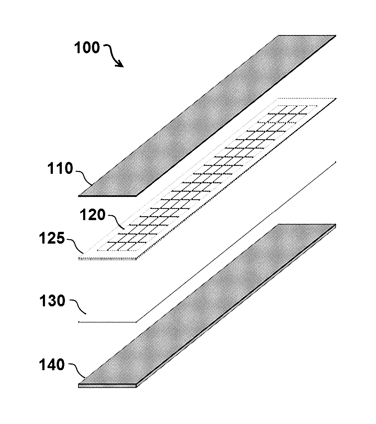
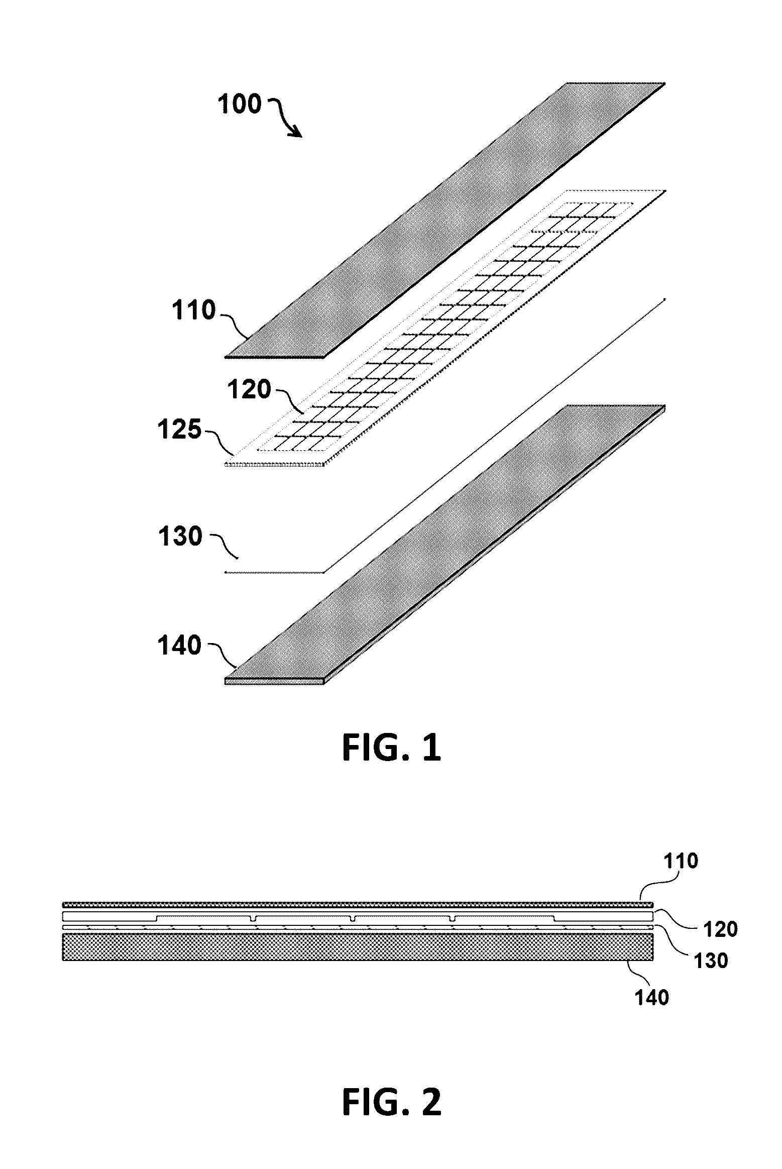
[0103]Referring initially to FIGS. 1-2, an exemplary embodiment of a device 100 configured as a thin film sensor comprises a diaphragm 110, a chamber structure 120, an adhesive 130 and a substrate 140. In the embodiment shown, diaphragm 110 is configured as a thin film diaphragm transducer between 10 μm and 20 μm thick and is bonded to substrate 140 via adhesive 130. In particular embodiments, diaphragm 110 is approximately 15 μm thick and substrate 140 is approximately 50 μm thick. In the present disclosure, the thickness of a material is measured across the primary plane of the material (i.e. the minimum dimension for a given layer of material, as would be measured in a vertical direction in the configuration shown in FIG. 2).

[0104]In the illustrated embodiment, chamber structure 120 comprises a bonding pad 125 around its perimeter and chamber structure 120 is positioned between diaphragm 110 and substrate 140. In exemplary embodiments of device 100, substrate 140 can be electrica...


PUM

PropertyMeasurementUnit
thickaaaaaaaaaa
thickaaaaaaaaaa
thickaaaaaaaaaa

Abstract

A thin-film, diaphragm based device is disclosed which can be used to perform an array of sensing and actuating operations where a very thin profile is desired, such as in millimeter, micrometer, or nanometer tight spaces.

Description

[0001]The application claims priority to U.S. Provisional Patent Application No. 61 / 914,473 filed Dec. 11, 2013, which is incorporated herein by reference in its entirety.BACKGROUND INFORMATION[0002]Most MEMS sensors are built onto silicon based wafers of approximately 500 μm thickness. While these thick substrates confer stability during fabrication and over the long term, the thickness limits applications in tight spaces, which includes many biomedical and industrial conditions. The rigidity and biocompatibility of silicon based sensors are additional limiting factors. Overcoming these issues is particularly challenging for diaphragm based sensors, due to the tight control required to build three-dimensional cavities and diaphragms at such a small scale.[0003]The active region of many silicon based sensors is the deflecting diaphragm near the surface of the sensor. Typically, the active region ranges from the low-micron to sub-micron scale, which is a small fraction of the overall...

Claims


Application Information

Patent Timeline
Patent Type & Authority Applications(United States)
IPC IPC(8): A61B5/00A61B5/103B29C65/48A61B5/1473A61M1/12A61F2/24A61B5/0215A61B7/02A61M60/135A61M60/268A61M60/438A61M60/531A61M60/554
CPCA61B5/6862B29L2031/753A61B5/0031A61B5/1038A61B7/023A61B5/1473A61B5/0084A61M1/125A61F2/24A61B5/1036B29C65/48A61B2562/028A61B2562/0285A61B2562/0247A61B2562/12A61B5/0215A61B5/0004A61B5/02158A61B5/145A61B2017/00345A61B2562/0204A61B2562/0233A61B2562/04A61B2562/164A61B5/03A61B5/026A61B5/032A61B5/6817A61B5/6852A61B5/686A61B8/0891A61B2562/16G01L9/0072A61M60/268A61M60/148A61M60/554A61M60/438A61M60/531B81B2201/0264
Inventor STARR, PETERBAILEY, STEVENAGRAWAL, MAULI
Owner BOARD OF RGT THE UNIV OF TEXAS SYST
Why Eureka
Try Eureka