
Apparatus for extracting oil from oil-bearing plants

a technology of oil-bearing apparatus and oil-bearing plant, which is applied in the direction of fatty-oil/fat production, separation process, fatty substance production, etc., and can solve the problem that the heating jacket of this publication does not supply heat and cold to the interior of the separator vessel

Active Publication Date: 2016-10-20
ELLIS MATTHEW
View PDF0 Cites 16 Cited by
  • Summary
  • Abstract
  • Description
  • Claims
  • Application Information

AI Technical Summary

Benefits of technology

The invention aims to provide a device and technique for extracting oil from raw plant material in a simple and low-cost way.

Problems solved by technology

However, the heating jacket of this publication does not supply heat and cold to the interior of the separator vessel and the expansion filter and help evaporate and condense the solvent.
However, this design provides for the use of filter only at the bottom of the extraction zone.

Method used


Image

  • Apparatus for extracting oil from oil-bearing plants
  • Apparatus for extracting oil from oil-bearing plants
  • Apparatus for extracting oil from oil-bearing plants

Examples


Embodiment Construction

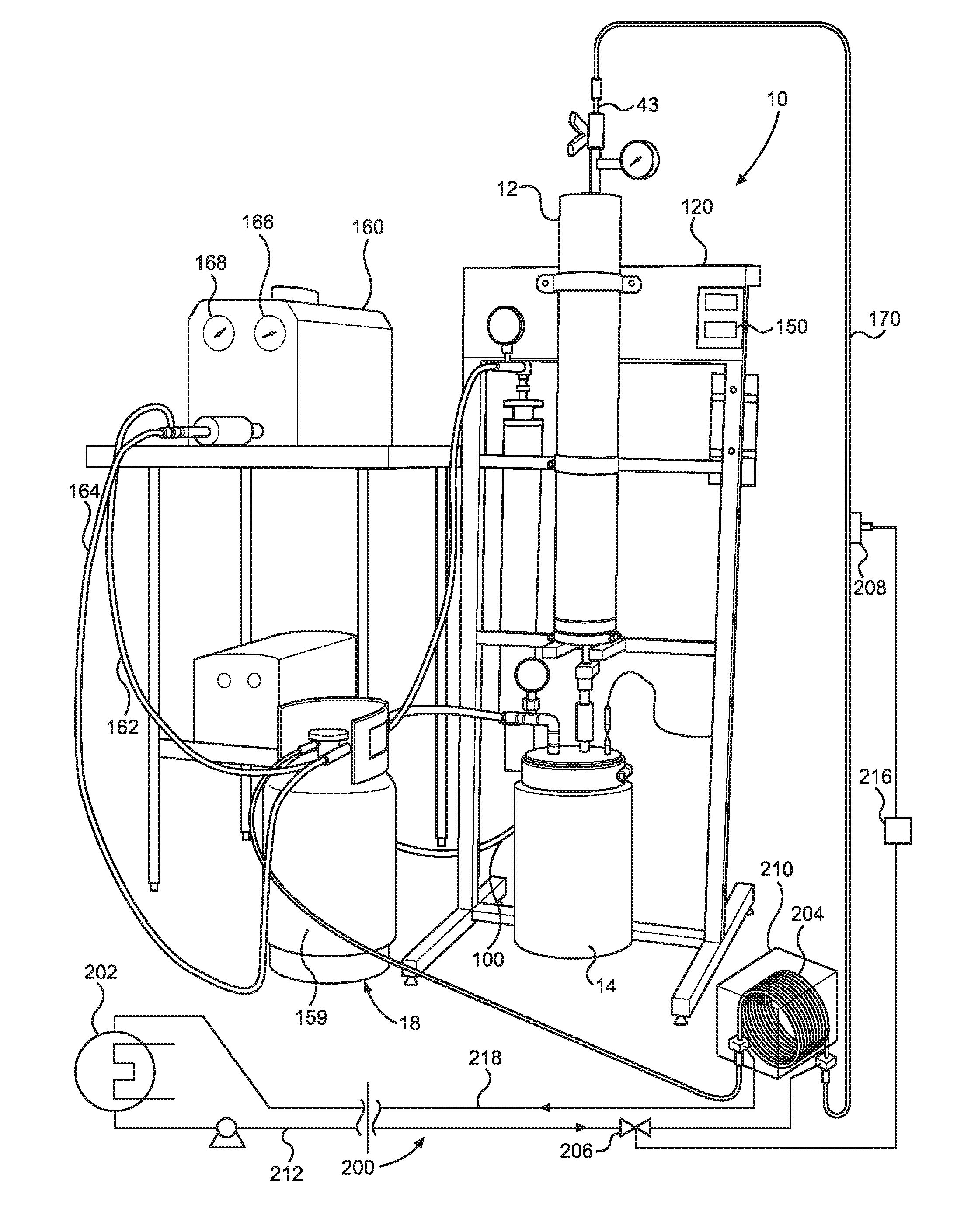
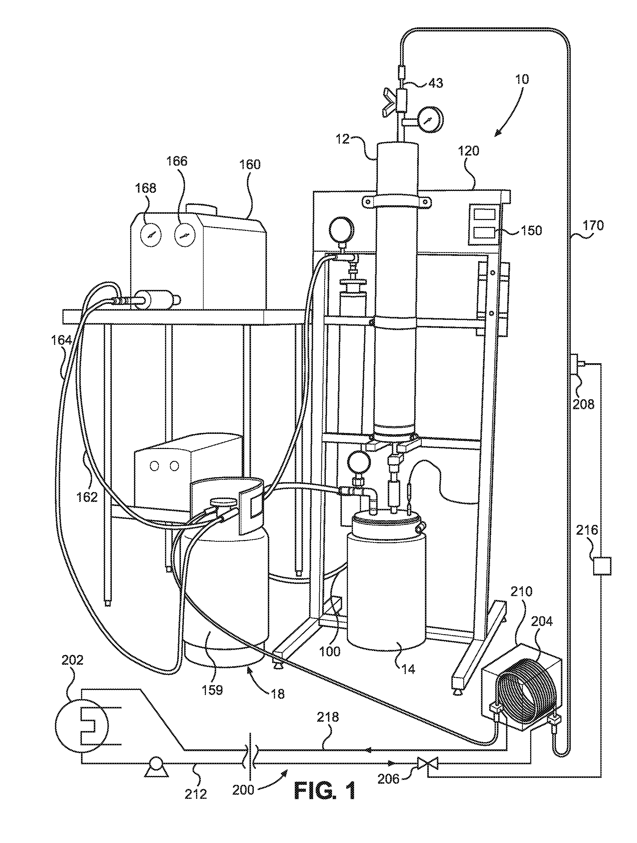
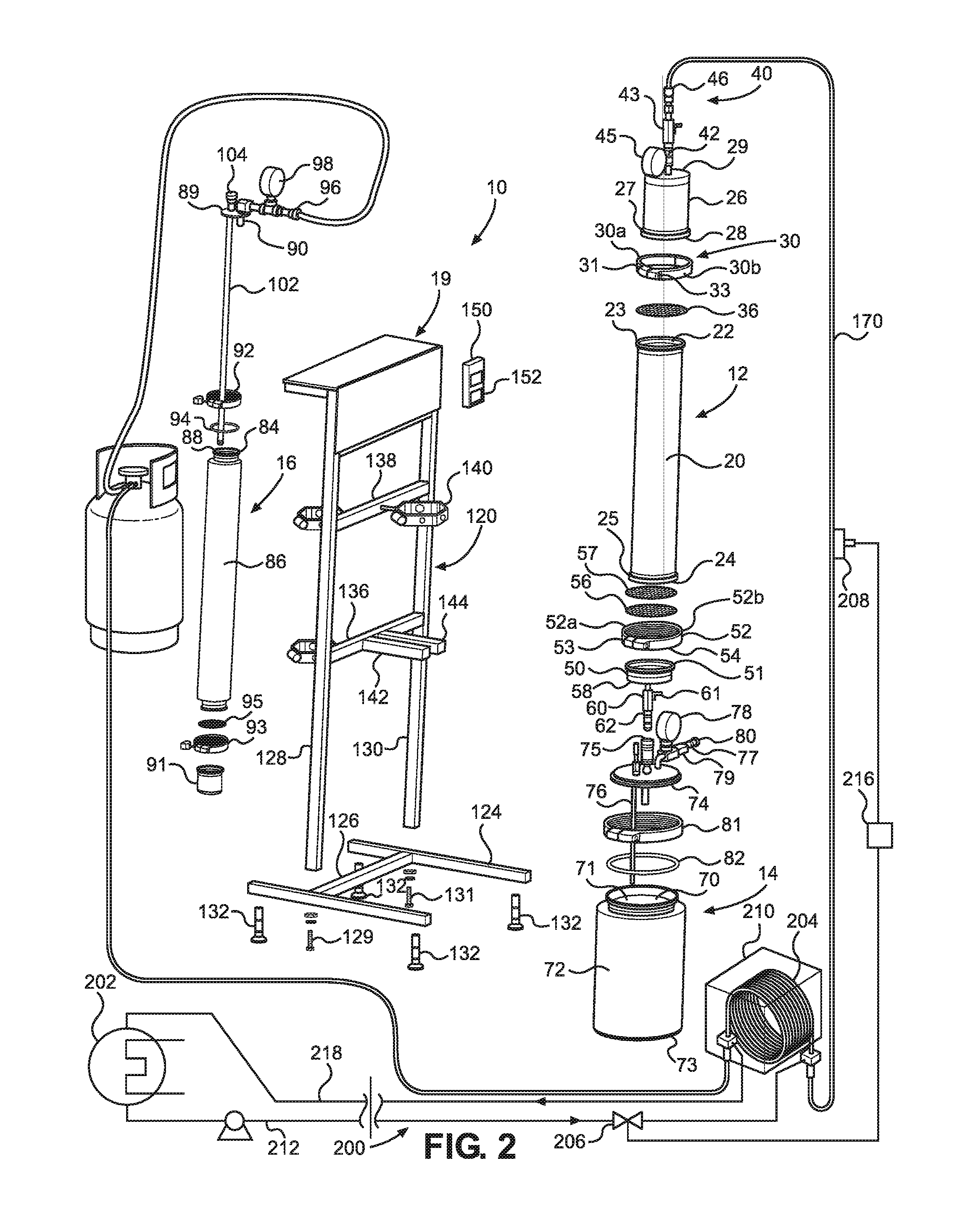
[0025]Turning now to the drawings in more detail, numeral 10 designates the system of plant oil extraction according to this invention. The system 10 comprises an extraction assembly 12, a separator assembly 14, an expansion filter assembly 16, a solvent recovery assembly 18, and an upright support assembly 19, which supports the extraction assembly 12 and the expansion filter assembly 16. If desired, the support assembly 19 can also support the separator assembly 14.

[0026]The extraction assembly 12 comprises a tubular hollow extraction vessel 20 from having an open top 22 and an open bottom 24. A peripheral flange 23 extends outwardly from the open top 22. A similar peripheral flange 25 extends outwardly from the open bottom 24.

[0027]A top cup 26 normally detachably engages with the open top 22. The top cup has an open bottom 28 that matches the size and configuration of the top open end 22 of the extraction vessel 20. The top cup 26 is provided with a peripheral flange 27 that mat...


PUM


Abstract

A system for extracting oil from oil-bearing plant parts has an extraction vessel supported by an upright stand, a separator vessel mounted below the extraction vessel, and an expansion filter vessel mounted downstream from the separator vessel. A source of hydrocarbon solvent supplies liquid gas to the top of the extraction vessel, while a recycling pump connected to the separator vessel facilitates transport of the solvent through the plant material in the extraction vessel. The solvent is recovered and re-circulated, while extracted oil is removed from the separator. A computer-based temperature control assembly having a cooling device and a jacketed injection coil regulates temperature of the solvent delivered to the extraction assembly. A thermal jacket is mounted on each of the separator vessel and the expansion filter vessel, with the thermal jackets supplying heat and cold to the interior of the separator vessel and the expansion filter vessel and helping evaporate and condense the solvent.

Description

CROSS-REFERENCE TO RELATED APPLICATIONS[0001]This application is a continuation-in-part of my co-pending application Ser. No. 14 / 470,494, filed Aug. 27, 2014, titled “An Apparatus for Extracting Oil from Oil-Bearing Plant Material,” which is a continuation-in-part of application Ser. No. 13 / 734,915, filed Jan. 4, 2013 for “An Apparatus for Extracting Oil from Oil-Bearing Plant Material,” now abandoned, the full disclosures of which are incorporated by reference herein and priority of which is hereby claimed.BACKGROUND OF THE INVENTION[0002]This invention relates to an apparatus and method of extracting oil from oil bearing plant parts, and more particularly to an apparatus and method of extracting plant oil using a hydrocarbon solvent agent.[0003]Plant oils have been extracted from plant material for centuries. Many plant oils are extracted from seeds by squeezing or crushing the seeds to force out the oil therefrom. Mechanical oil extractors or expellers are extensively used for ob...

Claims


Application Information

Patent Timeline
IPC IPC(8): B01D11/02C11B1/10
CPCB01D11/0207C11B1/104B01D11/0215B01D11/0292B01D11/0288B01D11/00B01D11/0203B01D11/028B01D2011/007C11B1/10
Inventor ELLIS, MATTHEW
Owner ELLIS MATTHEW
Learn More