Rfid-based smart terminal, bank card and financial management system

a smart terminal and rfid technology, applied in the field of radio frequency (rf) communication, can solve the problems of insufficient reliability, stability and read lifetime, and increased power consumption, and achieve the effects of reducing the activation time of the rfid antenna, saving energy, and reducing power consumption

Active Publication Date: 2016-10-20
HUIZHOU TCL MOBILE COMM CO LTD
View PDF4 Cites 153 Cited by
  • Summary
  • Abstract
  • Description
  • Claims
  • Application Information

AI Technical Summary

Benefits of technology

[0004]A main technical problem to be addressed by the present disclosure is to provide an RFID-based smart terminal, bank card and financial management system, which can enable the RFID function of the smart terminal to be turned on when needed and turned off When not needed, and thus can reduce its activation time and the power consumption.
[0014]Beneficial effects of the present disclosure follow as below: differing from the prior art, the smart terminal of the present disclosure senses via a sensor switch the nearing of an RFID signal source and thus activate the RFID antenna of the smart terminal, and proceeds to receive RFID signals in order to enable RFID function. The prevent disclosure would activate the RFID antenna by the trigger of the source only when the RFID signal source is nearing and the RFID function is needed, so as to prevent the RFID antenna from being activated all the time, thus reducing the activation time of the RFID antenna and effectively reducing the power consumption and saving energy.

Problems solved by technology

A traditional bank card generally uses a contact-based or mechanical way such as a magnetic strip read interface and an IC card read interface to implement data read and transmission, with insufficient reliability, stability and read lifetime.
When a bank card containing the RFID enters the induction zone of the RFID antenna of the smart terminal, RFID communication can be enabled therebetween, The RFID of a current smart terminal, however, would be turned on all the time in order to sense a nearing bank card, causing relatively greater power consumption.

Method used


Image

  • Rfid-based smart terminal, bank card and financial management system
  • Rfid-based smart terminal, bank card and financial management system
  • Rfid-based smart terminal, bank card and financial management system

Examples


first embodiment

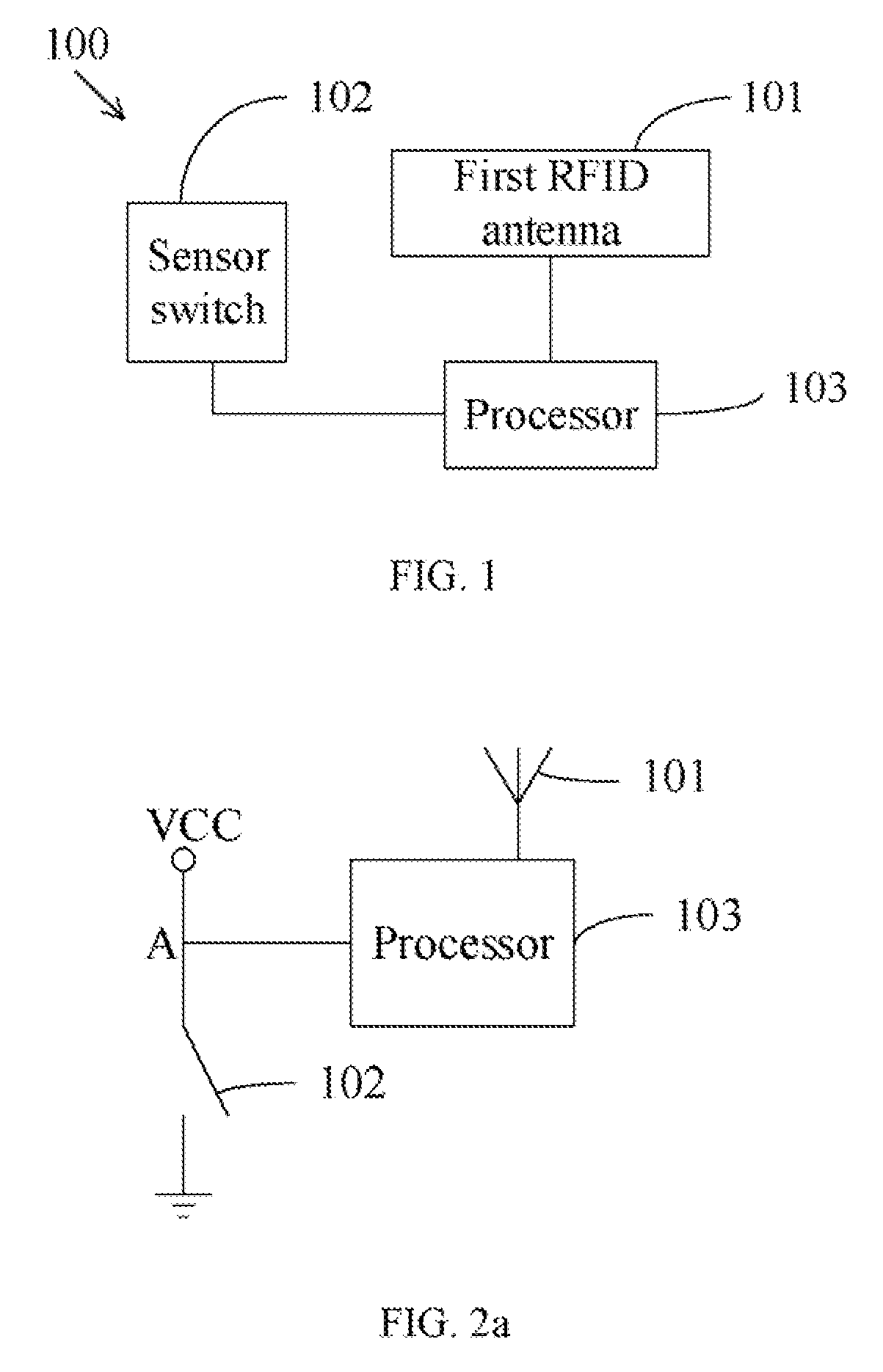
[0026]Referring now to FIG. 1, there is shown a block diagram illustrating an MD-based smart terminal according to the present disclosure. This embodiment provides an RFID-based smart terminal 100, comprising a first RFID antenna 101, a sensor switch 102 and a processor 103 connected respectively to the first RFID antenna 101 and the sensor switch 102.

[0027]The first RFID antenna 101 is configured to receive RFID signals.

[0028]In this embodiment, the first RFID antenna 101 is attached to the interior of the housing of smart terminal 100, thus enabling the transmission of RFID signals to be uninterrupted and smoother. To make the internal hardware configuration of the smart terminal 100 more optimized, the first RFID antenna 101 can, of course, be arranged at any location in smart terminal 100, on the premise that the first RFID antenna 101 can receive the RFID signals.

[0029]Smart terminal 100 serves as a read / write device of RFID tags. The first RFID antenna 101 serves as a communic...


PUM


Abstract

An RFID-based smart terminal, bank card and financial management system are disclosed. The smart terminal comprises a first RFID antenna, a sensor switch and a processor. The first RFID antenna is configured to receive RFID signals. The sensor switch is configured to, when sensing the approach of an RFID signal source, activate the first RFID antenna directly or through the processor so as to enable RFID function. The smart terminal according to the present disclosure can, when sensing the approach of the RFID signal source, trigger the first RFID antenna a to be activated, and can effectively reduce the power consumption and save energy.

Description

FIELD OF THE DISCLOSURE[0001]The present disclosure relates to the field of radio frequency (RF) communication, and more particularly, to an RFID-based smart terminal, bank card and financial management system.BACKGROUND OF THE DISCLOSURE[0002]RFID is an alphabetism for Radio Frequency Identification, generally referred to as an electronic tag. RFID is a technology of using radio frequency to perform non-contact one-way or two-way data transmission between a RF card and a reader. An RFID tag can be used as a unique electronic code to indentify a target object, and can, when compared with a traditional one-dimensional or two-dimensional code, store large amounts of data, with better security, longer service life, etc.[0003]More and more domains are thus beginning to use RFID technology, for example, a bank card embedded with an RFID tag. A traditional bank card generally uses a contact-based or mechanical way such as a magnetic strip read interface and an IC card read interface to im...

Claims


Application Information

Patent Timeline
Patent Type & Authority Applications(United States)
IPC IPC(8): G06Q20/34H04B5/00G06K19/07
CPCG06Q20/341G06K19/0705G06Q20/3278H04B5/0093G06Q20/354H04B5/0062G06K19/0716G06K19/0723G06K19/07345G06Q20/352H04B5/0025H04B5/0075Y02D30/70
Inventor GUO, GEORGEHU, XUELONG RONALDZHAO, SHIQING
Owner HUIZHOU TCL MOBILE COMM CO LTD
Why Eureka
Try Eureka