
Power circuit with low total harmonic distortion

Inactive Publication Date: 2016-10-20
ANWELL SEMICON CORP
View PDF1 Cites 2 Cited by
  • Summary
  • Abstract
  • Description
  • Claims
  • Application Information

AI Technical Summary

Benefits of technology

The present invention aims to provide a power circuit with low total harmonic distortion (THD) and high power conversion efficiency. The circuit utilizes a control chip to switch between three different power conversion modes: buck, boost, and buck-boost. The power storage element compensates for the high THD value produced by the output current, resulting in a low cost, high power, and low THD power circuit.

Problems solved by technology

Wherein, the boost power circuit with the advantages of low input current and low output voltage is commonly used as the circuit architecture for PFC Power Factor Correction (PFC) devices, but practical applications require higher voltage resisting components for the Pulse Width Modulation (PWM) control circuit and incur a high cost of the overall circuit, when the input voltage is 90V-260V and the output voltage is 400V-450V.
Although the buck power circuit does not have the aforementioned problem, yet the input current is not continuous, and thus the waveform of the input current is distorted significantly and contains higher harmonic waves of the output current.
The greater the output power, the higher level of difficulty to control the THD within a stable range.
Therefore, the product quality is unstable and such product cannot be introduced into some markets, and the industrial and economic values of the product are reduced.
If a safety component is added to stabilize the THD, the cost of the lamp will be increased, and the higher cost is disadvantageous to the sales competition.
In addition, the Buck-Boost architecture may be able to overcome the aforementioned problem, but there will be an efficiency loss as the sine wave of the input voltage drops, since the duty cycle ratio of the two power switches installed in the conventional circuit is close to the critical conditions of a full open circuit (with a duty cycle of 100%).
Furthermore, the input current and the output current are discontinuous and have the issues of electromagnetic interference and high output noises.

Method used


Image

  • Power circuit with low total harmonic distortion
  • Power circuit with low total harmonic distortion
  • Power circuit with low total harmonic distortion

Examples


Embodiment Construction

[0026]The technical content of the present invention will become apparent with the detailed description of preferred embodiments and the illustration of related drawings as follows.

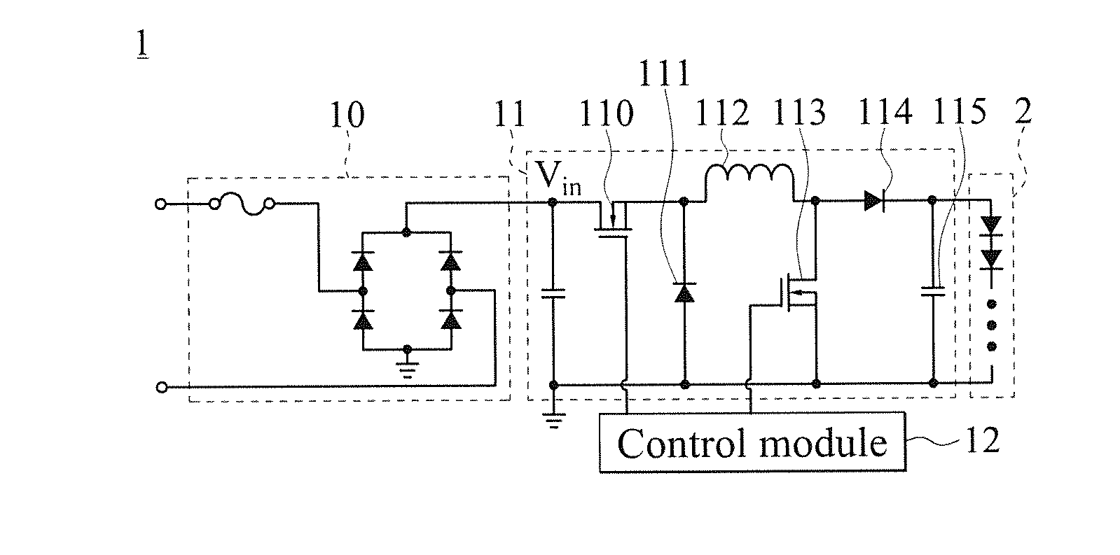
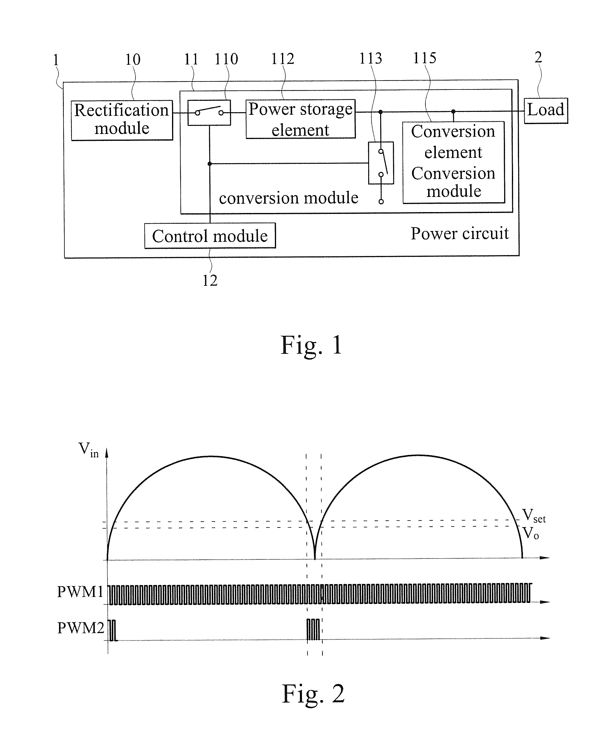
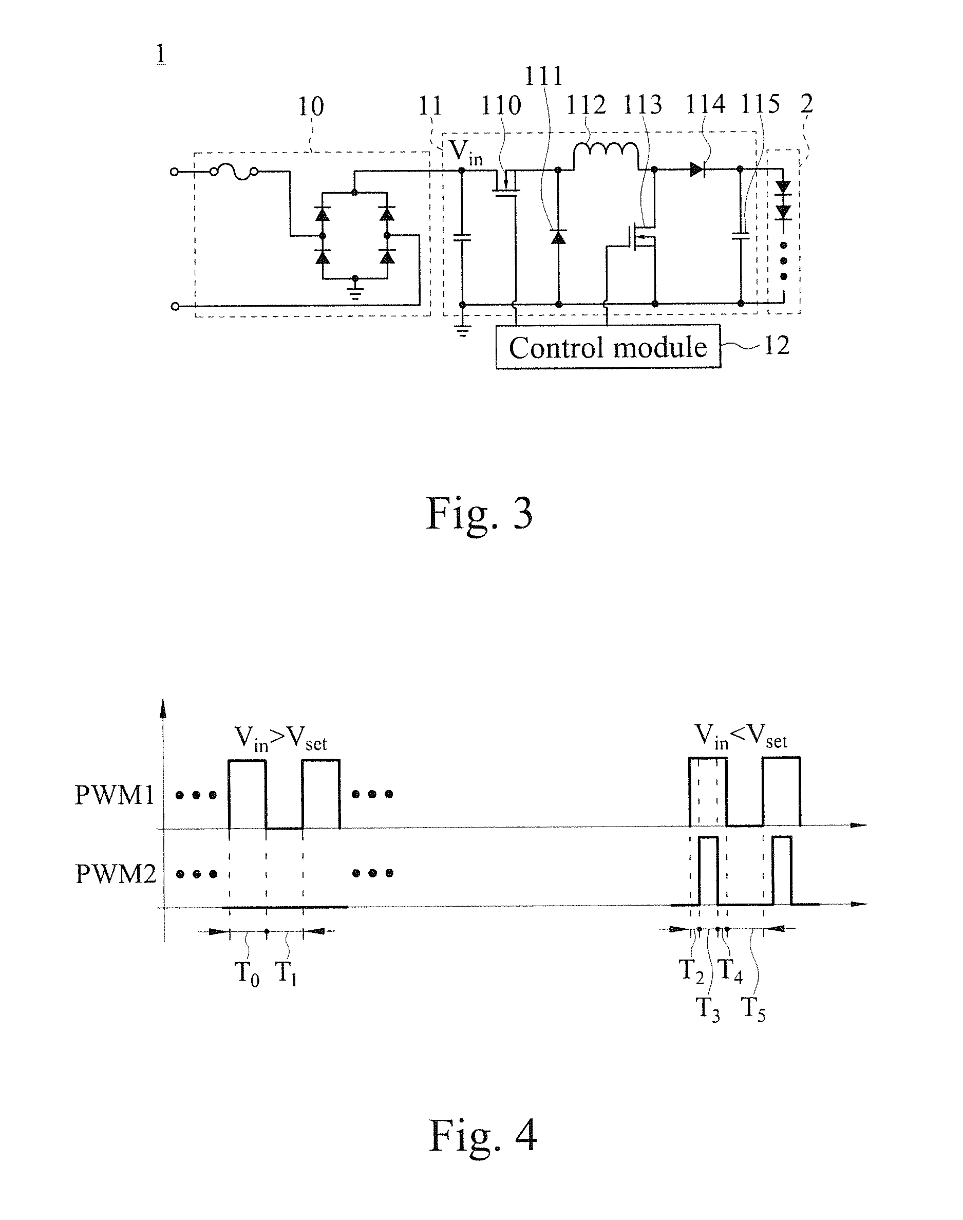
[0027]With reference to FIGS. 1-3 for a block diagram, a waveform chart and a circuit diagram of a power circuit with a low total harmonic distortion 1 in accordance with an implementation mode of a preferred embodiment of the present invention respectively, the power circuit with a low total harmonic distortion 1 comprises a rectification module 10, a conversion module 11 and a control module 12, wherein the rectification module 10 is electrically coupled to an external power supply (not shown in the figure) and the conversion module 11, and the conversion module 11 is electrically coupled to at least one load 2 and the control module 12. The rectification module 10 is a bridge rectifier for rectifying the current of an AC voltage of the external power supply to form an input voltage (Vin) and then suppl...


PUM


Abstract

A power circuit with a low total harmonic distortion includes a conversion module and a control module, and the conversion module includes a first switch, a second switch, a power storage element and a conversion element. Both ends of the power storage element are electrically connected to the first switch, the second switch and the conversion element. Trigger ends of the first and second switches are electrically connected to the control module. If the input voltage is smaller than a predetermined value, the control module will output a control pulse to the second switch, and the second switch will conduct and drive the power storage element to boost the input voltage to generate a compensating current in a timing cycle, and the second switch will cut off and allow the compensating current to be converted into a voltage form by the conversion element and outputted in another timing cycle.

Description

BACKGROUND OF THE INVENTION[0001]1. Field of the Invention[0002]The present invention relates to the field of power supply equipments, and more particularly to a power circuit with a low total harmonic distortion (THD) that will start a current compensation to reduce the THD value of the overall circuit if the input voltage of the circuit is smaller than a predetermined value.[0003]2. Description of the Related Art[0004]In general, a power supply provided for driving the operation of various electronic devices converts AC voltage and power of the mains power to generate a driving voltage or current required by an electronic device. To output a stable voltage or current, the power supply generally adopts the Pulse Width Modulation (PWM) control method to control the output voltage or current value. In various different power supplies, the switching power supply (SPS) with the features of high efficiency, small volume, light weight, easy assembling and large scope of output voltage is...

Claims


Application Information

Patent Timeline
IPC IPC(8): H02M1/12H02M7/06
CPCH02M7/06H02M1/12H02M1/4225H02M3/1582Y02B70/10
Inventor CHEN, KE-HORNGCHIU, SHAO-WEIKUO, CHUN-CHIEHTU, SHIH-PINGHSIAO, CHENG-PO
Owner ANWELL SEMICON CORP
Learn More