Tplo bone plate

a bone plate and tplo technology, applied in bone drill guides, medical science, surgery, etc., can solve problems such as damage to the articular and periarticular surfaces, and achieve the effects of reducing the bending of the tplo plate, and shortening the surgical procedur

Active Publication Date: 2016-10-27
MWI VETERINARY SUPPLY
View PDF13 Cites 20 Cited by
  • Summary
  • Abstract
  • Description
  • Claims
  • Application Information

AI Technical Summary

Benefits of technology

[0007]In aspects of some examples of the invention, a new TPLO plate is provided which is better tailored to the TPLO procedure especially when the cut is made fairly high on the upper tibia. The lower leg section or elongated shaft remains aligned or mostly aligned with respect to the lower tibia and yet the head portion conforms to the cut rotated upper tibial portion. Inter-operative bending of the TPLO plate may be minimized. One result is a shortening of the surgical procedure and less metal fatigue. The two tibial sections are properly secured together and the bone screws used properly hold the bone plate in place after the operation. The bone screws are prevented from extending into the stifle. It is preferred that the new TPLO plate is anatomically pre-contoured so the elongated shaft portion is aligned with the long axis of the tibia to allow for more bone purchase by screws (e.g., longer screws can be used) and greater stiffness while at the same time providing a better fit of the head portion to the rotated portion of the tibia.

Problems solved by technology

The result can also be bone plates which do not properly secure the two tibia sections together, bone screws which do not properly hold (shorter bone screws may have to be used) and / or which extend into the stifle (knee) joint causing damage to the articular and periarticular surfaces possibly leading to osteoarthritis.

Method used


Image

  • Tplo bone plate
  • Tplo bone plate
  • Tplo bone plate

Examples


Embodiment Construction

[0033]Aside from the preferred embodiment or embodiments disclosed below, this invention is capable of other embodiments and of being practiced or being carried out in various ways. Thus, it is to be understood that the invention is not limited in its application to the details of construction and the arrangements of components set forth in the following description or illustrated in the drawings. If only one embodiment is described herein, the claims hereof are not to be limited to that embodiment. Moreover, the claims hereof are not to be read restrictively unless there is clear and convincing evidence manifesting a certain exclusion, restriction, or disclaimer.

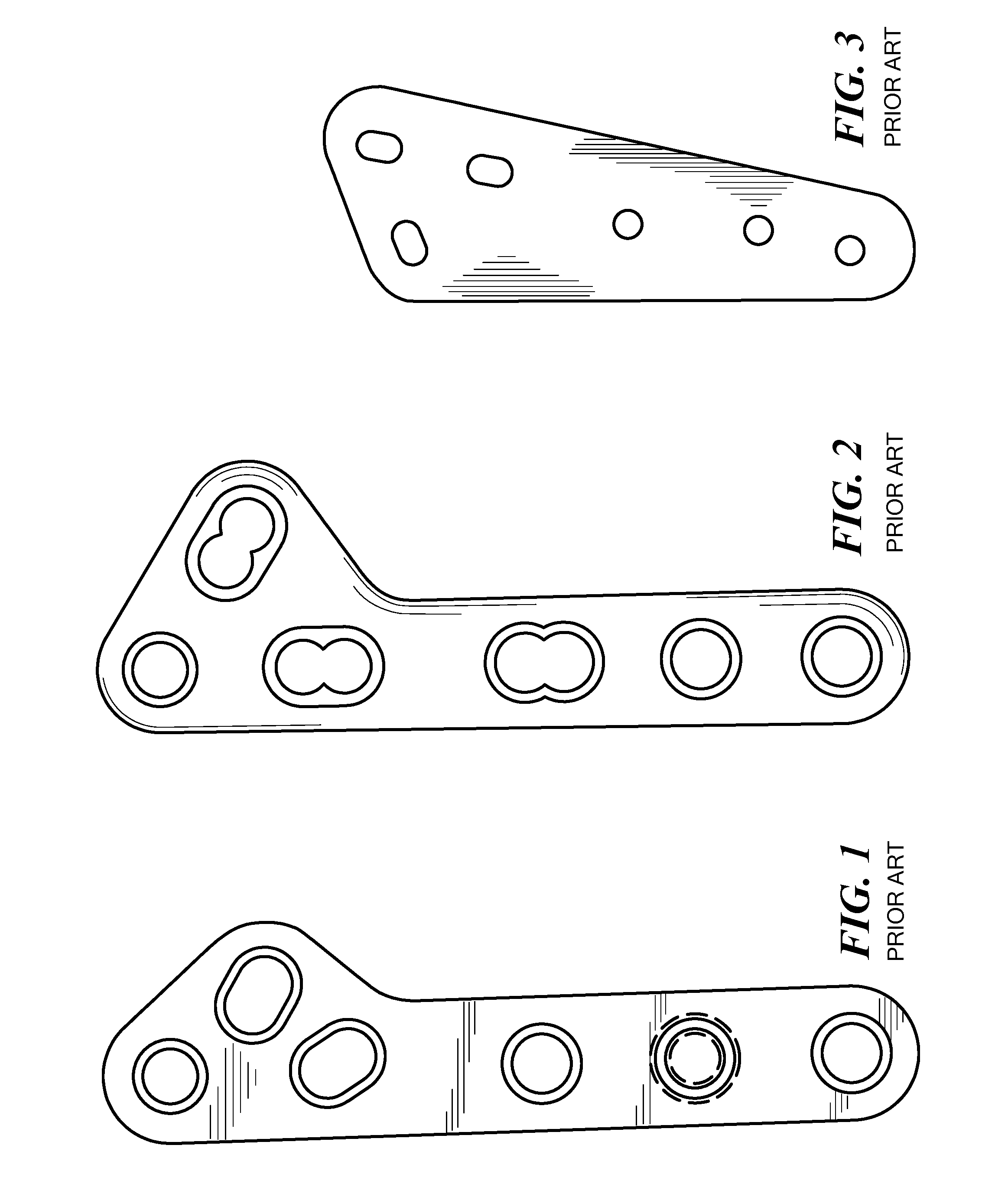
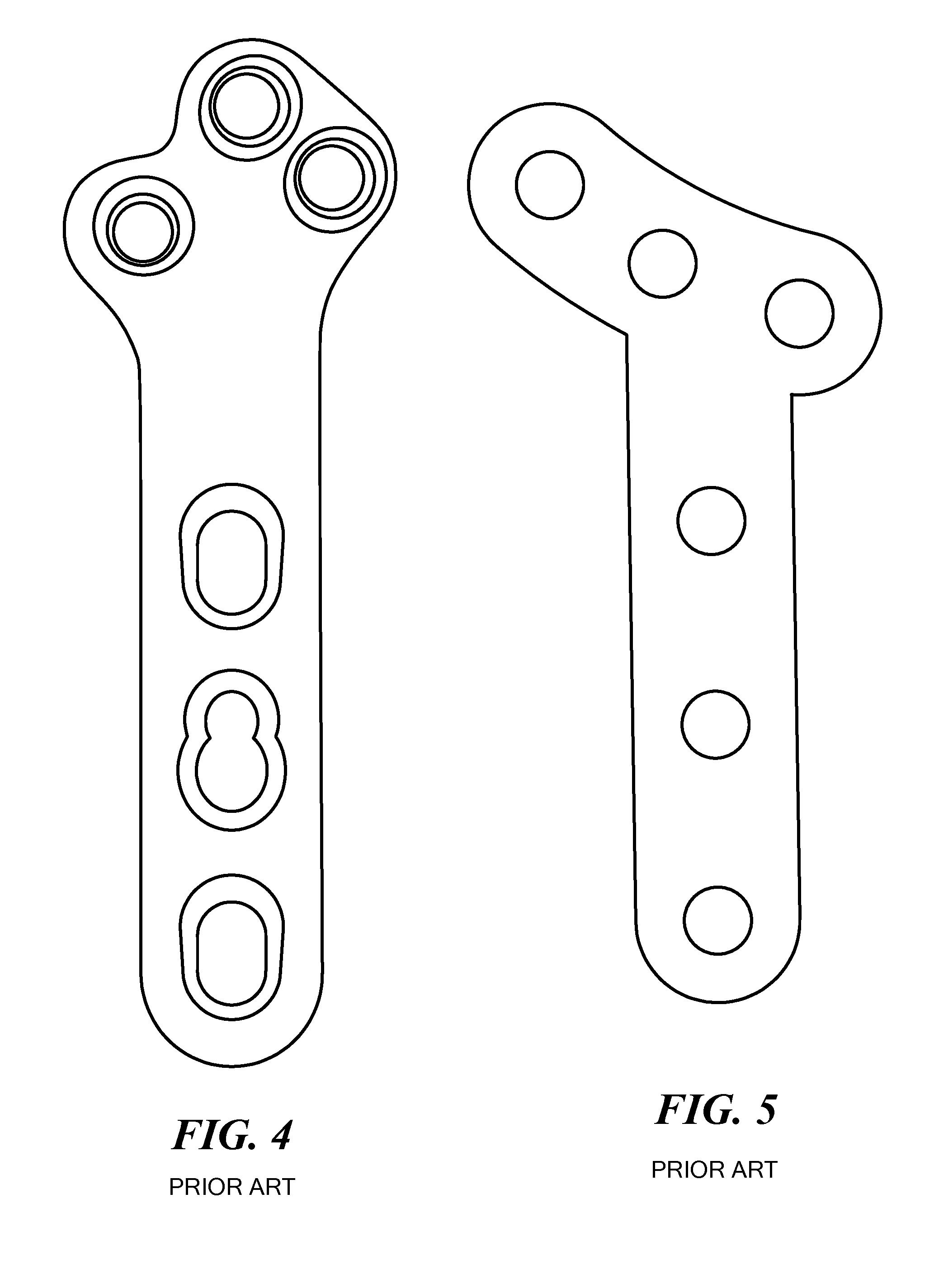
[0034]FIGS. 1-5 show various prior art TPLO bone plates which may not be optimized or specifically tailored for a TPLO procedure where the cut is made fairly high on the upper tibia. Some prior TPLO bone plates may require that the lower leg section or shaft portion be angled with respect to the lower tibia. In some prior a...


PUM


Abstract

A bone plate is dimensioned for securing the rotated cut segment of an upper tibia to the lower portion of the tibia as part of a tibial leveling osteotomy procedure for an animal. The bone plate includes an elongated shaft, a head portion pre-bent with respect to the elongated shaft, and a transition between the elongated shaft and head portion including opposing concave sidewalls. The elongated shaft has a centerline and the pre-bent head portion has a centerline angled with respect to the centerline of the elongated shaft to dispose the elongated shaft collinear or approximately collinear with respect to the lower portion of the tibia and to better fit the head portion to the rotated cut segment of the upper tibia.

Description

RELATED APPLICATIONS[0001]This application claims benefit of and priority to U.S. Provisional Application Ser. No. 62 / 150,524 filed Apr. 21, 2015, under 35 U.S.C. §§119, 120, 363, 365, and 37 C.F.R. §1.55 and §1.78, which is incorporated herein by this reference.FIELD OF THE INVENTION[0002]This invention primarily relates to a bone plate dimension for securing the rotated cut segment of an upper tibia to the lower portion of the tibia as part of a tibial leveling osteotomy procedure for an animal.BACKGROUND OF THE INVENTION[0003]The purpose of the tibial plateau leveling osteotomy (TPLO) procedure is to stabilize the cranial cruciate ligament (CCL)—deficient canine stifle by reducing the tibial plateau slope thereby neutralizing the cranial tibial thrust force or redirecting it into a caudal direction. See, for example, Kowaleski, et al. “The Effect of Tibial Plateau Leveling Osteotomy Position on Cranial Tibial Subluxation: An In Vitro Study, Veterinary Surgery, 34:332-336 (2005), ...

Claims


Application Information

Patent Timeline
Patent Type & Authority Applications(United States)
IPC IPC(8): A61B17/80A61B17/17
CPCA61B17/1739A61B17/8061A61B17/1728A61B17/8052
Inventor KAZANOVICZ, ANDREW J.ANDERSON, III, DAVID J.
Owner MWI VETERINARY SUPPLY
Why Eureka
Try Eureka