
Alkaline water electrolysis diaphragm, method of manufacturing same, and alkaline water electrolyzer

a technology of alkaline water and electrolysis diaphragm, which is applied in the direction of electrolysis components, organic diaphragms, cells, etc., can solve the problems of increasing the frequency of diaphragm replacement, not being economical, and deteriorating the productivity of hydrogen and oxygen, so as to improve the manufacturability, improve the chemical strength, and improve the effect of hydrophilicity and chargeability of the polymer porous layer

Inactive Publication Date: 2016-10-27
DE NORA PERMELEC LTD +2
View PDF0 Cites 12 Cited by
  • Summary
  • Abstract
  • Description
  • Claims
  • Application Information

AI Technical Summary

Benefits of technology

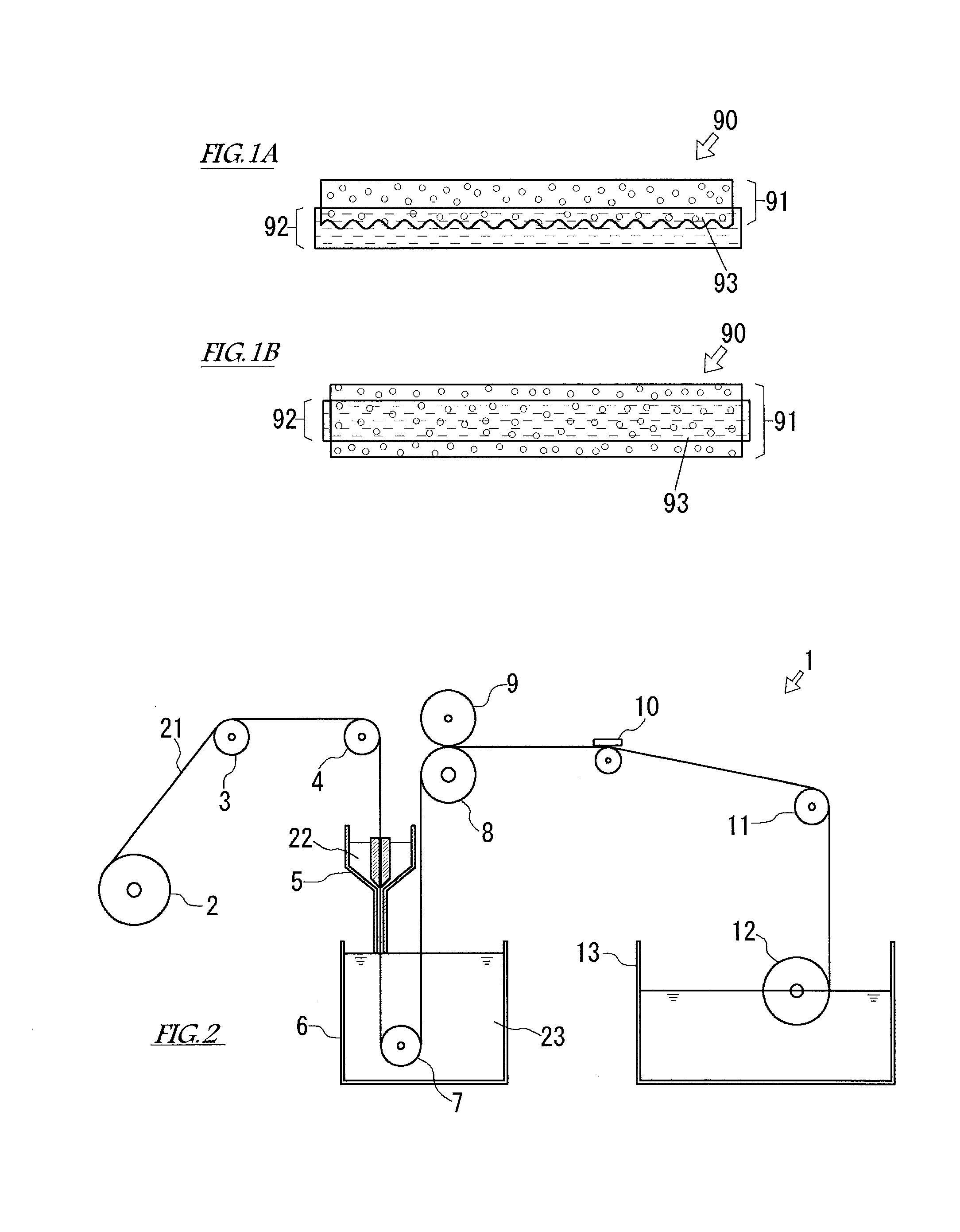
The invention is an alkaline water electrolysis diaphragm that includes a polymer porous layer and an organic fiber fabric layer. The polymer porous layer has excellent chemical strength and maintains the hydrophilicity and chargeability of polyether sulfone and polysulfone. The alkaline water electrolysis diaphragm also has good gas barrier property and electrolysis efficiency. The organic fiber fabric layer compensates for the physical strength of the polymer porous layer, improving the manufacturability.

Problems solved by technology

If the diaphragm is worn away, the frequency of replacement of the diaphragm increases, and this is not economical.
In addition, a problem is that the productivity of hydrogen and oxygen deteriorates.
This compensates the physical strength and the manufacturability, which cannot be adequately obtained only by the polymer porous membrane.
It should be noted that the polymer porous membrane containing polyether sulfone or polysulfone as the major component has a certain degree of physical strength but does not satisfy the physical strength or manufacturability required in the diaphragm of the alkaline water electrolyzer.

Method used


Image

  • Alkaline water electrolysis diaphragm, method of manufacturing same, and alkaline water electrolyzer
  • Alkaline water electrolysis diaphragm, method of manufacturing same, and alkaline water electrolyzer
  • Alkaline water electrolysis diaphragm, method of manufacturing same, and alkaline water electrolyzer

Examples


example 1

[0060]A diaphragm according to Example 1 was obtained by a nonsolvent induction phase separation method using, as the hydrophilic polyether sulfone, polyether sulfone (Sumikaexcel (trademark) 5003PS produced by Sumitomo Chemical Company, contact angle of 65 to 74°, rate of hydroxyl group per polymer repeating unit of 89%) having a hydroxyl group at its terminal and also using, as the fabric, PPS non-woven fabric (Torcon paper (trademark) PS0100 produced by Toray Industries, Inc., thickness of 0.21 mm, density of 0.48 to 0.55 g / cm3). Specifically, first, the hydrophilic polyether sulfone was added to N-methyl-2-pyrrolidone (produced by Daishin Chemical Co., Ltd.) at a concentration of 15 wt. % and stirred for 24 hours to obtain an adequately uniform solution. The solution was left at rest for 24 hours to adequately remove bubbles from the solution. Thus, the membrane forming solution was prepared. Next, fabric was spread on a glass plate, and the membrane forming solution was applied...

example 2

[0061]A diaphragm according to Example 2 was obtained by a nonsolvent induction phase separation method using polysulfone (Ultrason (trademark) S6010 produced by BASF Japan Ltd., molecular weight of 50,000, contact angle of 85 to 90°, rate of hydroxyl group per polymer repeating unit of 0) and PPS non-woven fabric (Torcon paper (trademark) PS0100 produced by Toray Industries, Inc.). Specifically, the polyether sulfone was added to N-methyl-2-pyrrolidone (produced by Daishin Chemical Co., Ltd.) at a concentration of 15 wt. %, and the membrane forming solution was prepared in the same manner as in Example 1. By using this membrane forming solution, the diaphragm was obtained in the same manner as in Example 1. The thickness of the diaphragm according to Example 2 was 500 to 700 μm.

REFERENCE EXAMPLES

[0062]In Reference Examples, polymer porous membranes simulating the porous layer constituting the diaphragm for the alkaline water electrolyzer were produced.

reference example 1

[0063]A polymer porous membrane according to Reference Example 1 was obtained by a nonsolvent induction phase separation method using polyether sulfone (Sumikaexcel (trademark) 5003PS produced by Sumitomo Chemical Company) having a hydroxyl group at its terminal. Specifically, first, the hydrophilic polyether sulfone was added to N-methyl-2-pyrrolidone (produced by Daishin Chemical Co., Ltd.) at a concentration of 15 wt. % and stirred for 24 hours to obtain an adequately uniform solution. The solution was left at rest for 24 hours to adequately remove bubbles from the solution. Thus, the membrane forming solution was prepared. Next, the membrane forming solution was uniformly applied to a smooth glass plate at a predetermined thickness. The glass plate to which the membrane forming solution was applied was then immersed in a chemical liquid (water) to remove the organic solvent. The formed membrane was removed from the glass plate. Thus, the polymer porous membrane was obtained. The...


PUM


Abstract

An alkaline water electrolysis diaphragm includes: a polymer porous layer containing at least one polymer compound selected from polyether sulfone having a contact angle of 20 to 90° and polysulfone having the contact angle of 20 to 90°; and an organic fiber fabric layer coupled to the polymer porous layer. The polyether sulfone having the contact angle of 20 to 90° is at least one polymer compound selected from the group made of polyether sulfone, hydrophilic polyether sulfone, cationic polyether sulfone, and cationic hydrophilic polyether sulfone. The polysulfone having the contact angle of 20 to 90° is at least one polymer compound selected from the group made of polysulfone, hydrophilic polysulfone, cationic polysulfone, and cationic hydrophilic polysulfone.

Description

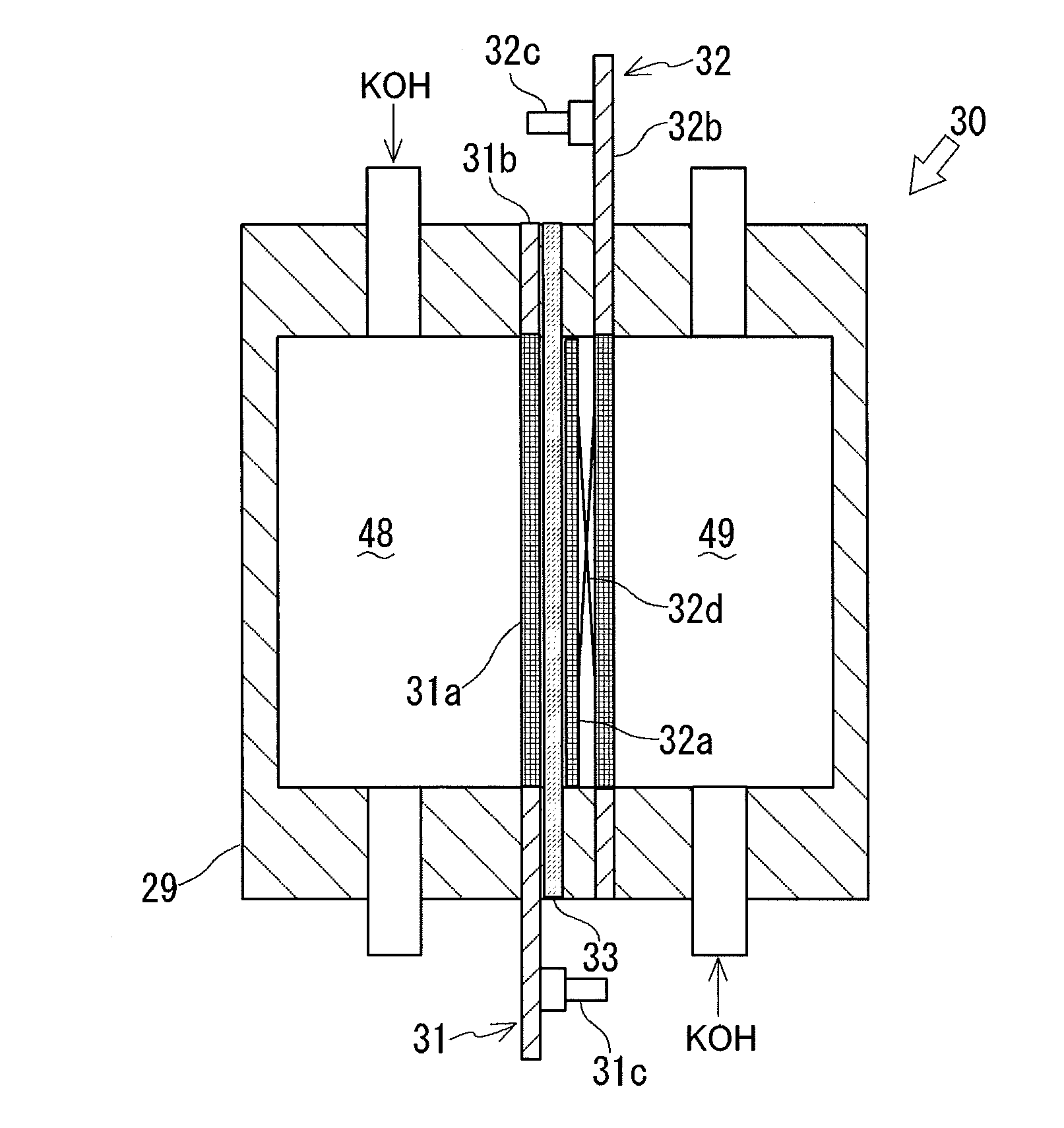
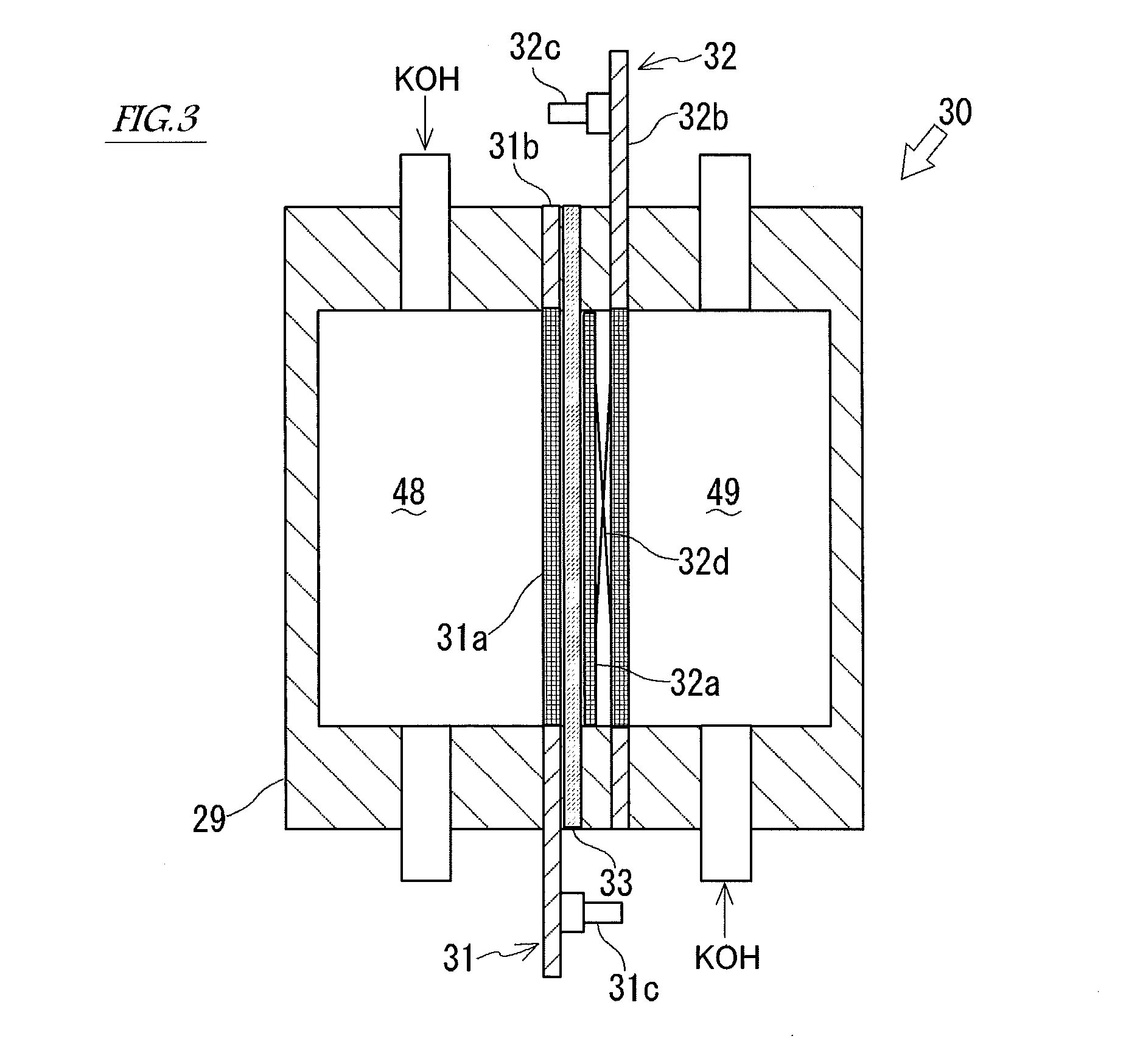
TECHNICAL FIELD[0001]The present invention relates to an alkaline water electrolyzer, an alkaline water electrolysis diaphragm, and a method of manufacturing the alkaline water electrolysis diaphragm.BACKGROUND ART[0002]An alkaline water electrolyzer configured to generate oxygen and hydrogen from water has been known. Typically, the alkaline water electrolyzer includes one or more electrolysis units. For example, the electrolysis unit of the alkaline water electrolyzer described in PTL 1 includes: an electrolysis tank; an alkali aqueous solution, such as a potassium hydroxide (KOH) aqueous solution, stored in the electrolysis tank; two mesh-like electrodes immersed in the alkali aqueous solution; a diaphragm held so as to be sandwiched between the two electrodes and having ion permeability; two power supply electrodes configured to supply electric power to the respective electrodes; and plate spring-shaped electrically-conductive members through which the power supply electrodes ar...

Claims


Application Information

Patent Timeline
IPC IPC(8): C25B13/08C25B1/10C25B9/08C25B9/19
CPCC25B13/08C25B1/10C25B9/08Y02E60/36C25B1/04C25B9/73C25B9/19
Inventor KAMEI, YUJITAGUCHI, KOKISHIMOMURA, IKUOITO, TAKAFUMIKAWAGUCHI, JUNTAKASE, TOMONORIKATO, AKIHIROMANABE, AKIYOSHIHASHIMOTO, TERUMI
Owner DE NORA PERMELEC LTD
Learn More