

Water closet
- Summary
- Abstract
- Description
- Claims
- Application Information
AI Technical Summary
Benefits of technology
Problems solved by technology
Method used
Image

Examples
Embodiment Construction
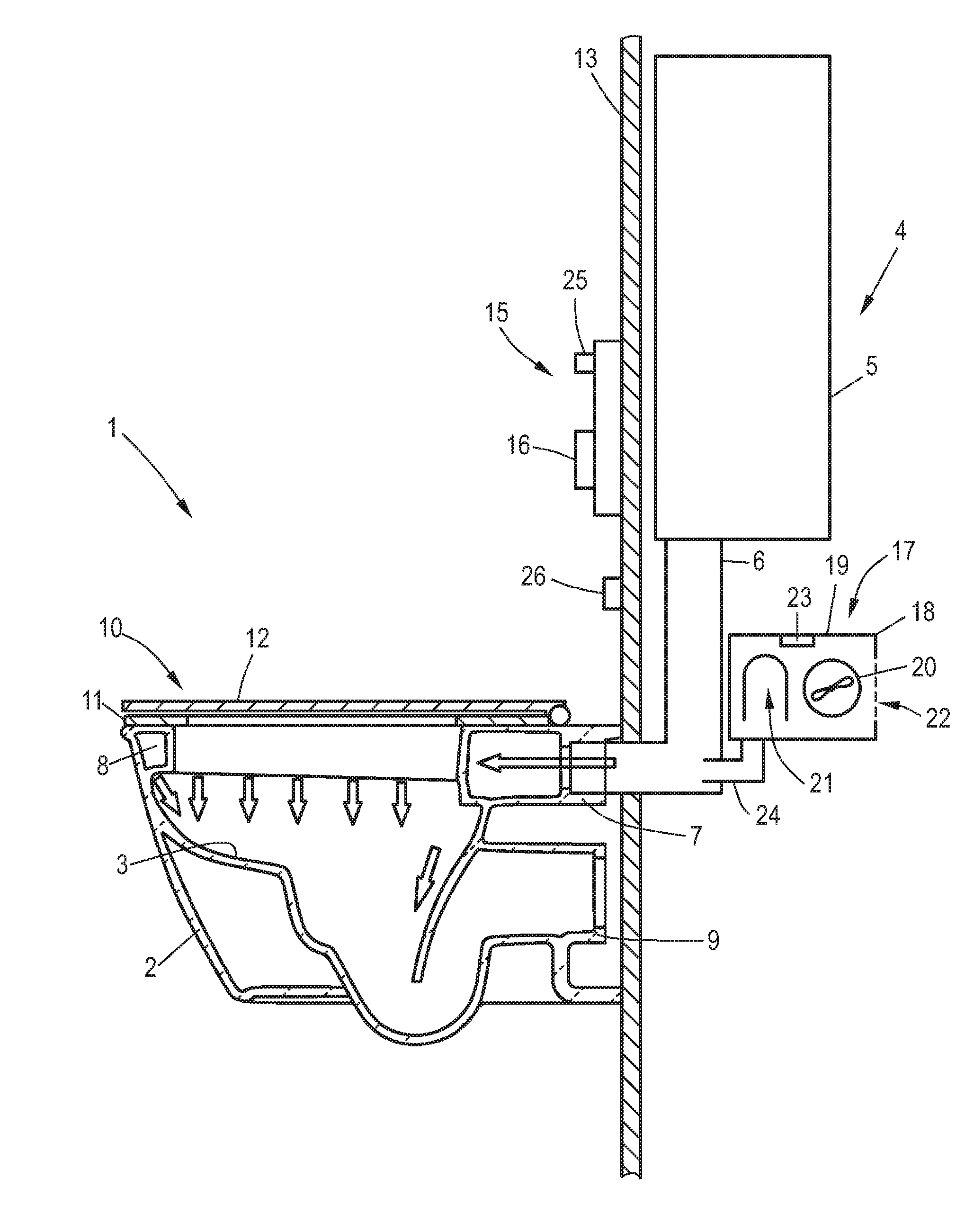
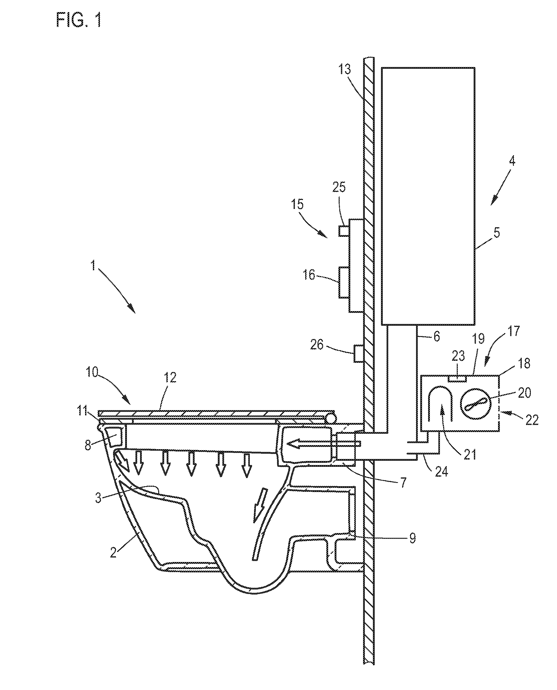
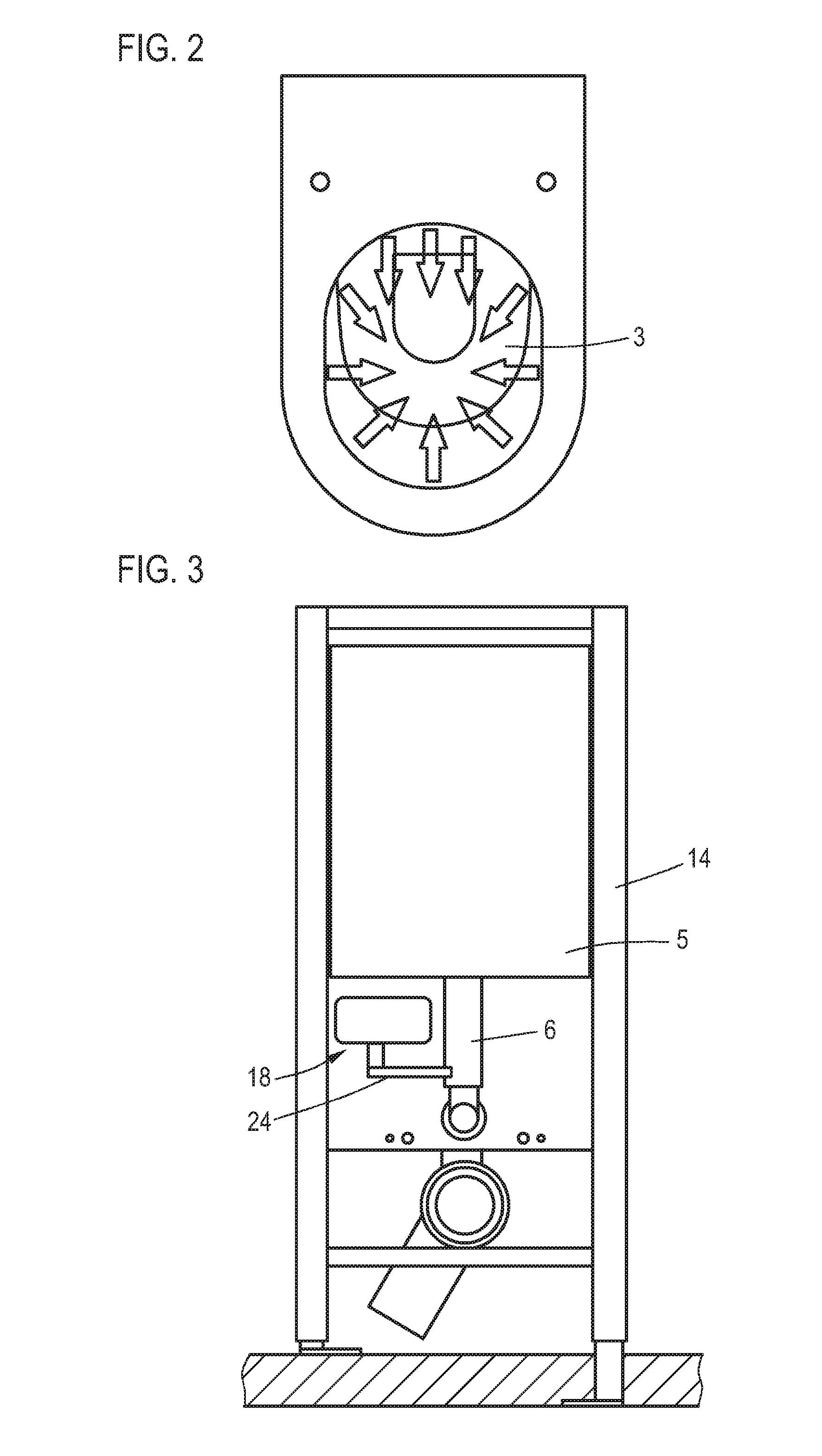
[0033]FIG. 1 shows a schematic diagram of a water closet 1 according to the invention comprising a flush toilet 2 with a bowl 3 (see also FIG. 2). Also provided is a flushing device 4, comprising a flush water tank 5 and a flush water feed line 6, through which the flush water tank 5 is connected to a connector socket 7 of the flush toilet, which is usually made of ceramic or porcelain. In the present example, the flush water entering through this feed line arrives in a water ring 8, through which it can flow into the bowl by way of appropriate perforations in the water ring 8. The arrows shown in FIGS. 1 and 2 show the basic way in which the flush water can potentially flow.
[0034]In a manner known in and of itself, the flush toilet naturally also comprises a connecting flange 9 for a wastewater line. Also mounted on the flush toilet is a seat-lid combination 10, comprising a seat 11 and a lid 12.
[0035]The flushing device 4 is installed behind a front wall 13, wherein a mounting fra...
PUM
 Abstract
Description
Claims
Application Information