
Architecture for long latency operations in emulated shared memory architectures

a shared memory and architecture technology, applied in the field of computer science and computer architectures, can solve the problems of destroying the performance of communication intensive problems, and affecting the execution speed of concurrent instruction, and affecting the performance of caches. and synchronicity maintenance,

Active Publication Date: 2016-10-27
TEKNOLOGIAN TUTKIMUSKESKUS VTT
View PDF6 Cites 3 Cited by
  • Summary
  • Abstract
  • Description
  • Claims
  • Application Information

AI Technical Summary

Benefits of technology

The objective of this patent is to address the problems of existing ESM arrangements and provide a solution for executing long latency operations, such as division or application-specific operations, effectively. There may also be one or more functional units located after the memory access segment, which units are preferably of lower latency.

Problems solved by technology

Unfortunately most SMAs use a distributed shared memory architecture consisting of multiple interconnected processor-cache pairs, which makes cache coherency (and therefore latency tolerance) and synchronicity maintenance very expensive.
This may even ruin their performance in communication intensive problems.
Since the throughput computing scheme employs parallel slackness extracted from the available thread-level parallelism, it is considered to provide enhanced scalability in contrast to traditional symmetric multiprocessors and non-uniform memory access (NUMA) systems relying on snooping or directory-based cache coherence mechanisms and therefore suffering from limited bandwidth or directory access delays and heavy coherence traffic maintenance.
Despite of the many aforementioned advantages, ESM systems have appeared difficult to realize in truly optimal fashion.
Execution of such complex or otherwise special operations could require additional logic or hardware, and take a greater number of clock cycles or generally just take longer, i.e. cause a longer latency, to complete in contrast to e.g. basic ALU operations.
Nevertheless, the latency caused by the associated elements and related processing taking place in the paths often adds to the overall execution time of instructions proceeding in the processor pipeline structure.

Method used


Image

  • Architecture for long latency operations in emulated shared memory architectures
  • Architecture for long latency operations in emulated shared memory architectures
  • Architecture for long latency operations in emulated shared memory architectures

Examples


Embodiment Construction

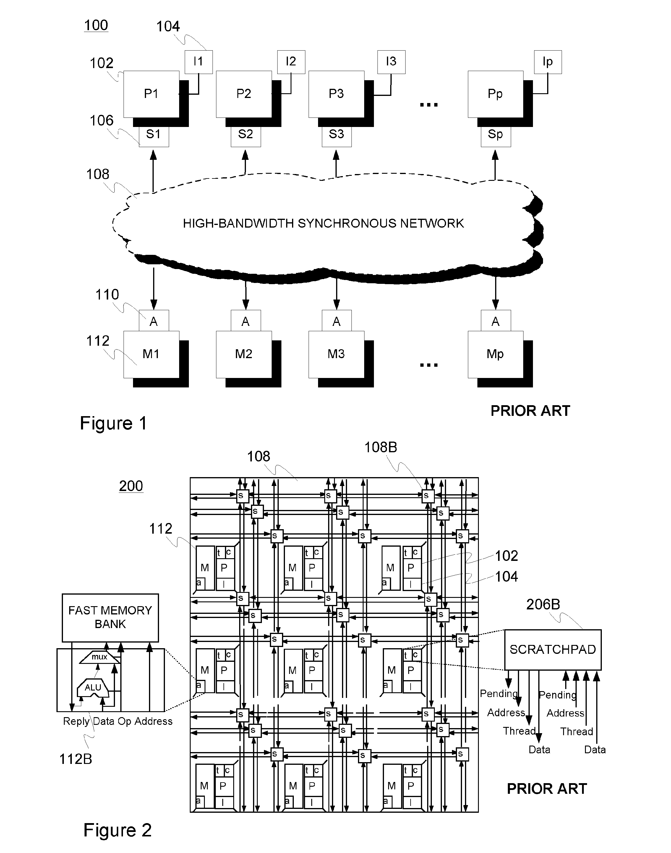
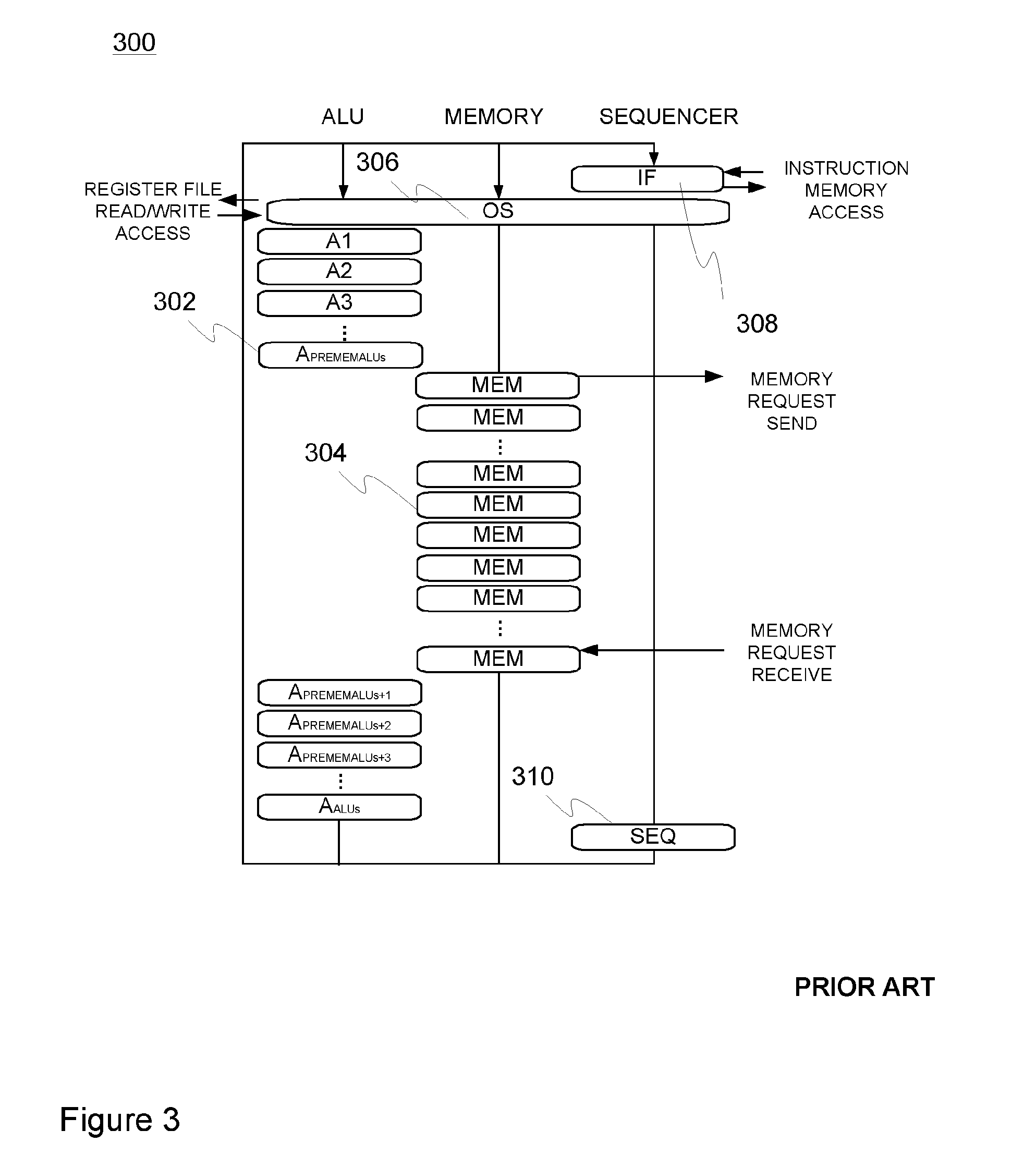
[0039]FIGS. 1-3 were already contemplated hereinbefore in connection with the description of both background and historical data relating to the origin of the present invention.

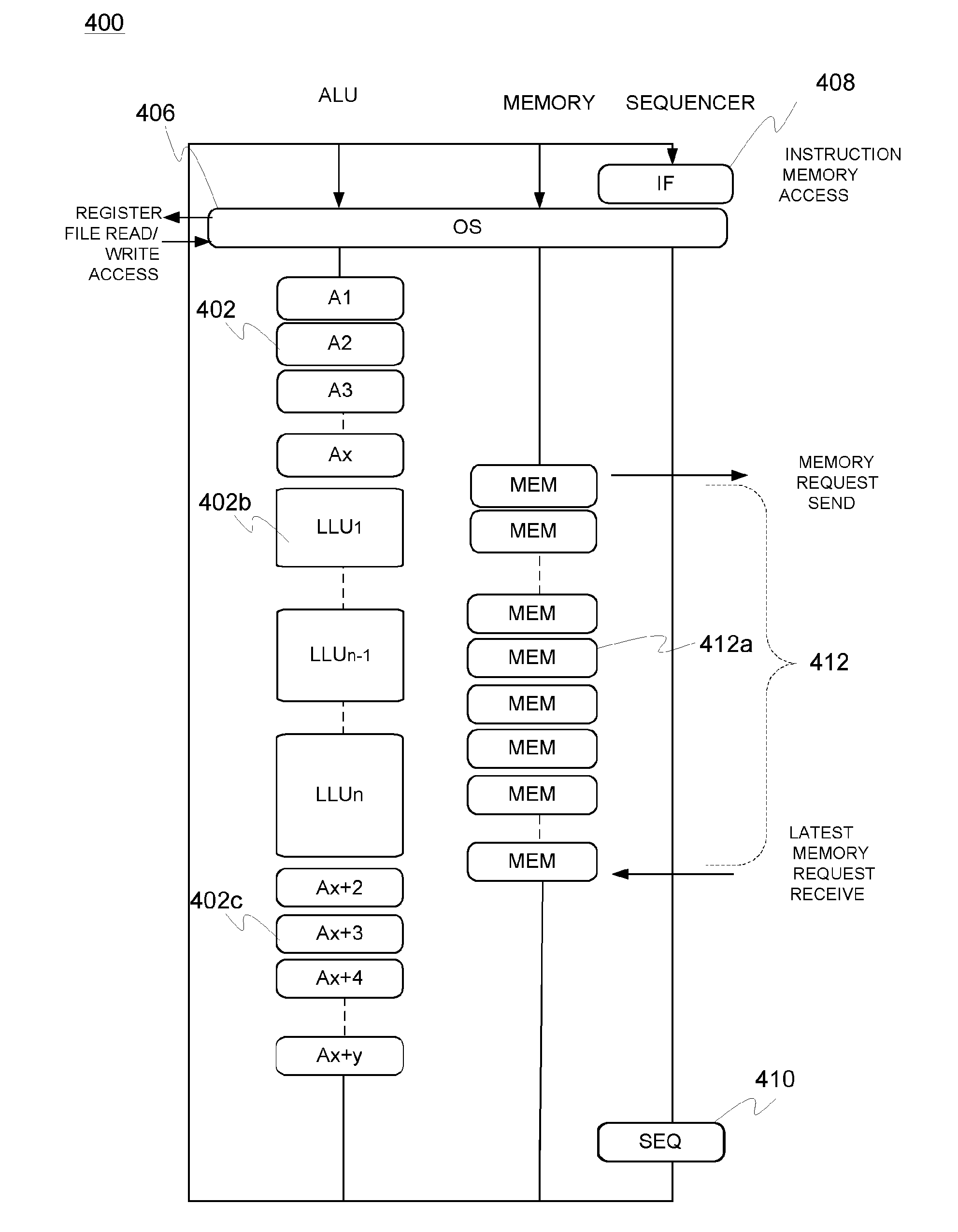
[0040]FIG. 4 illustrates one embodiment of the present invention incorporating ESM pipeline architecture 400 with a plurality (N) of long latency units (LLU) 402b as well as other functional units (FU) such as (ordinary or lower latency) ALUs 402, 402c. These other functional units such as ALUs may be positioned before 402 and after 402c the memory access segment 412 and thus, the LLUs 402b.

[0041]The layout of the functional units 402, 402b, 402c is merely exemplary in the figure and in other embodiments, the positioning, number and nature / latency thereof may diverge from the illustrated one. The functional units 402, 402b, 402c have been provided with unique identifiers in connection with general identifiers A(LU) and LLU to bring forward the fact that the units 402, 402b, 402c may mutually differ, also wit...


PUM


Abstract

A processor architecture arrangement for emulated shared memory (ESM) architectures, comprises a number of, preferably a plurality of, multi-threaded processors each provided with interleaved inter-thread pipeline, wherein the pipeline comprises a plurality of functional units arranged in series for executing arithmetic, logical and optionally further operations on data, wherein one or more functional units of lower latency are positioned prior to the memory access segment in said pipeline and one or more long latency units (LLU) for executing more complex operations associated with longer latency are positioned operatively in parallel with the memory access segment. In some embodiments, the pipeline may contain multiple branches in parallel with the memory access segment, each branch containing at least one long latency unit.

Description

FIELD OF THE INVENTION[0001]Generally the present invention pertains to computer science and computer architectures. In particular, the invention relates to the execution of long latency operations in connection with emulated shared memory architectures.BACKGROUND[0002]In SMAs (shared memory architecture), data and program partitioning is typically carried out by placing data requiring processing by multiple threads into the shared memory and splitting program more independently to processors, thus making programming easier compared to message passing (MPA) architectures in which processing happens always locally and the programmer is responsible for moving data around accordingly. Unfortunately most SMAs use a distributed shared memory architecture consisting of multiple interconnected processor-cache pairs, which makes cache coherency (and therefore latency tolerance) and synchronicity maintenance very expensive. This may even ruin their performance in communication intensive prob...

Claims


Application Information

Patent Timeline
IPC IPC(8): G06F9/38G06F9/30
CPCG06F9/3001G06F9/30029G06F9/3867G06F9/30058G06F9/3004G06F9/3873G06F9/3895
Inventor FORSELL, MARTTI
Owner TEKNOLOGIAN TUTKIMUSKESKUS VTT
Learn More