Eureka AIR delivers breakthrough ideas for toughest innovation challenges, trusted by R&D personnel around the world.

Diagnostic Method for Solar Power System and Monitoring Device

Active Publication Date: 2016-10-27
HITACHI LTD
View PDF3 Cites 8 Cited by
  • Summary
  • Abstract
  • Description
  • Claims
  • Application Information

AI Technical Summary

Benefits of technology

The present invention provides a diagnostic method for a large PV power generation system that can detect faults accurately without adding excess measurement and communication means. The method can distinguish between overall degradation and malfunctions.

Problems solved by technology

On the other hand, some modules undergo a sudden decrease in output due to manufacturing quality issues or physical damage.
The sudden decrease in output is considered a fault.
Methods for detecting faults in PV cell modules have included visual inspection, testing heat generation using a thermometer, and testing of electrical characteristics or transient responses using a tester, but such tests are performed one-by-one on PV cell modules or PV cell strings (a unit of PV cell modules connected in series), which poses the issue of increased labor and costs required for testing in the case of a large-scale PV power plant.
Furthermore, while there are automated test methods in general use in which a measurement means and a communication means are set for each PV cell module or string, this does not fully address the issue of cost increase due to reasons including the reliability of the measurement means.
Employing the techniques of Patent Documents 1-3 does solve the problem of enabling determination of faults in the PV power system without additional measurement means or communication means, but the comparison of the reference value with the evaluation value such as in Patent Document 1 presents the problem that determination accuracy cannot be improved due to varying solar radiation and temperature conditions.
The number of actinometers and thermometers is limited to one or at most a few per large-scale PV power plant, which means that a method in which solar radiation information and temperature information are used such as in Patent Document 2 would also not improve measurement accuracy.
Patent Document 3 poses the problem that due to the PV cell array to be measured itself being evaluated using an actinometer and thermometer and fault information being extracted while performing feedback, accuracy is high but it is impossible to distinguish overall degradation from a fault.

Method used


Image

  • Diagnostic Method for Solar Power System and Monitoring Device
  • Diagnostic Method for Solar Power System and Monitoring Device
  • Diagnostic Method for Solar Power System and Monitoring Device

Examples


embodiment 1

[0025]Embodiment 1 pertains to a diagnostic method for a photovoltaic (PV) power system in which the intensity of solar radiation (insolation) on a PV cell array is determined according to operating current and voltage of a PV cell array during two selected time periods while changing the series resistance, which is a cause parameter for overall degradation, an operating temperature and fault value of the PV cell array are calculated using the operating voltage and solar radiation intensity, and computation is repeated until the fault values calculated for the respective time periods match, thereby distinguishing loss as a result of a faulty module present in the PV cell array from loss as a result of overall degradation.

[0026]Before explaining the embodiments, properties of a PV power system and PV cells in a large-scale PV power plant to which the embodiments are applied will be described.

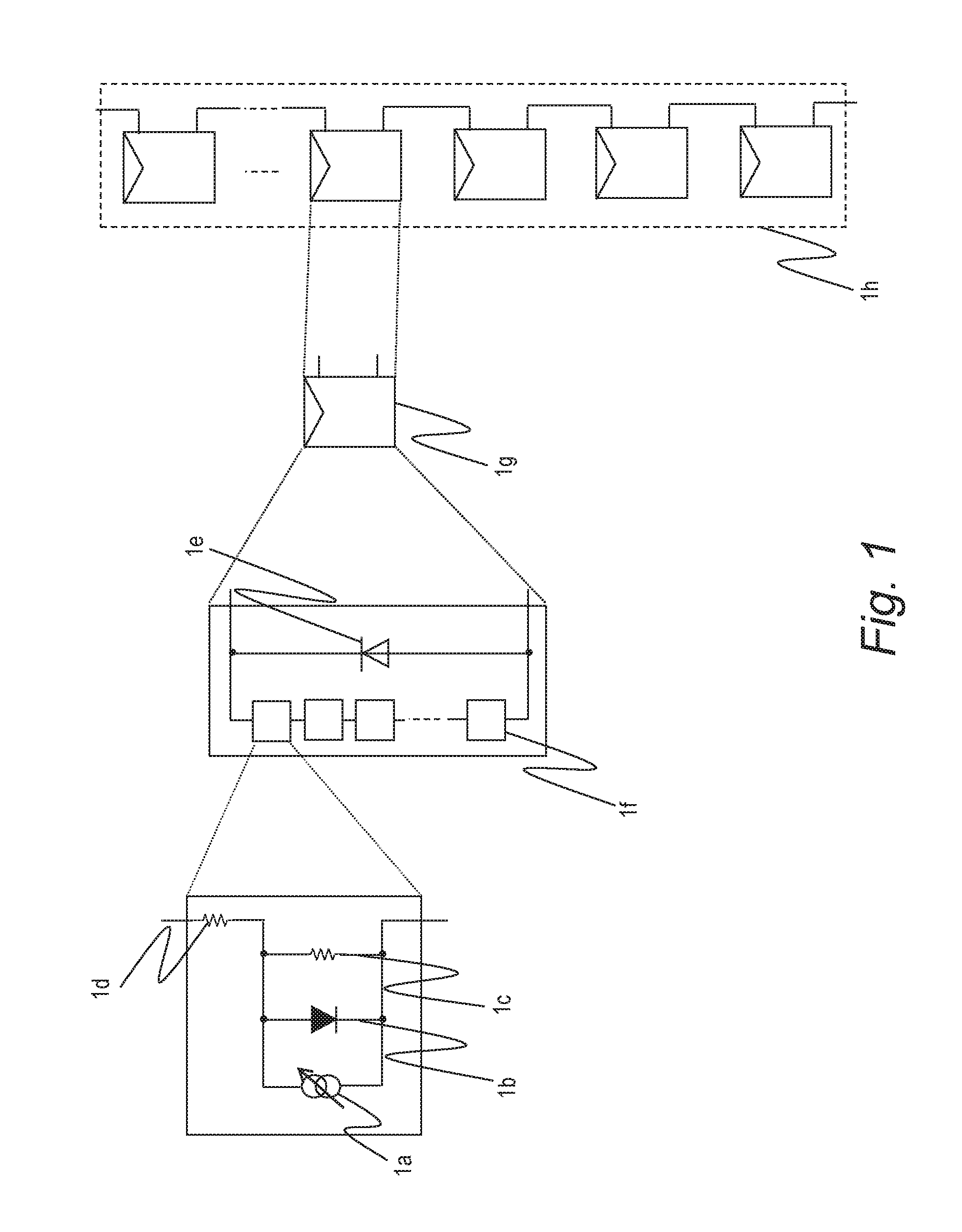
[0027]FIG. 1 is a descriptive view of an example of a configuration of a PV cell string accor...

embodiment 2

[0087]Next, Embodiment 2 of a diagnostic method for a PV power system will be described. Aside from the differences described below, the various components of the system of Embodiment 2 have the same functions as the components of Embodiment 1 that are displayed in FIGS. 1 to 8B and that are assigned the same reference characters, and thus, descriptions thereof are omitted.

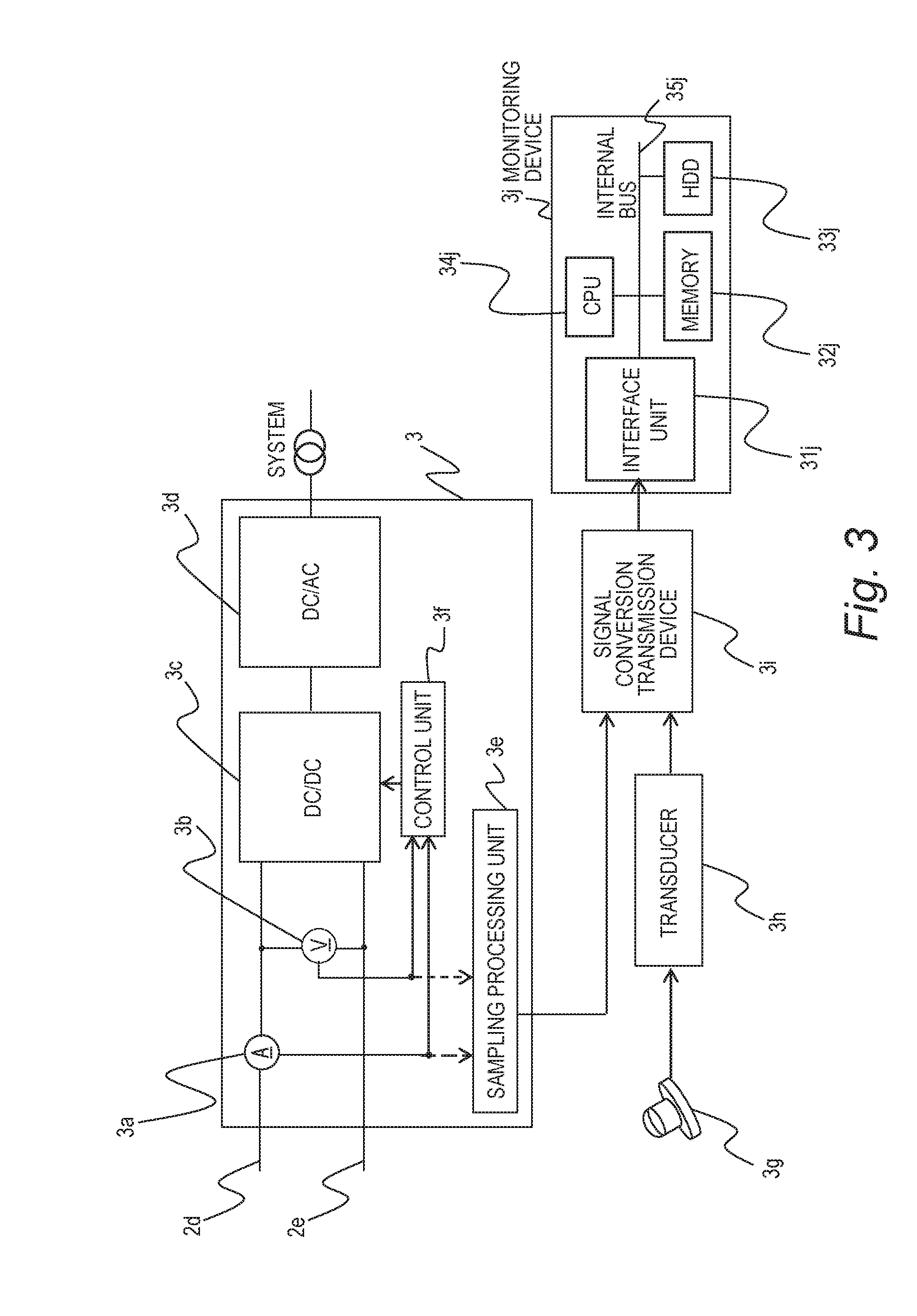
[0088]During the two selected time periods, the monitoring device 3j of Embodiment 2 does not estimate initial characteristics of the PV cell array, but first performs the two processes of calculating the solar radiation amount incident on the PV cell array and calculating the estimated temperature of the PV cell array, determines the fault value including overall degradation (loss resulting from series resistance), and calculates the series resistance according to the difference between the fault value 1 and fault value 2. Details of these processes will be explained below.

[0089]As shown in FIGS. 5A and 5B, if lo...


PUM


Abstract

The diagnostic method for a photovoltaic power system includes: a step of storing measured values of voltage and current outputted by a photovoltaic cell array, and identifying a first time period and a second time period with a lower solar radiation amount than in the first time period; a step of calculating the number of faulty photovoltaic cells on the basis of the measured values in the first time period; a step of calculating the number of faulty photovoltaic cells on the basis of the measured values in the second time period; and a step of comparing the number of faulty photovoltaic cells as calculated for the first time period, and the number of faulty photovoltaic cells as calculated for the second time period, and identifying a series resistance of the photovoltaic cells and a value indicating a degree of loss resulting from a fault in the photovoltaic cells.

Description

CLAIM OF PRIORITY[0001]The present application claims priority from Japanese patent application JP2015-88192 filed on Apr. 23, 2015, the content of which is hereby incorporated by reference into this application.BACKGROUND OF THE INVENTION[0002]The present invention relates to a fault diagnosis technique by which fault diagnosis of a photovoltaic (PV) module is performed in a PV power system constituted of multiple PV cell modules.[0003]Examples of techniques for fault diagnosis of a PV power system are disclosed in JP 2012-114108 A (Patent Document 1), JP 2012-54401 A (Patent Document 2), and JP 2014-45073 A (Patent Document 3).[0004]Patent Document 1 discloses the following: “the power generation amounts are acquired and stored, the power generation amounts for an evaluation time of a sampling period are calculated, the greatest power generation amounts therein are extracted, and the average thereof is set as a reference value. Also, the power generation amounts during the evaluat...

Claims


Application Information

Patent Timeline
IPC IPC(8): H02S50/00G01R27/02
CPCG01R27/02H02S50/00Y02E10/50
Inventor KOUNO, TORUKUBO, ATSUHIKONAGAYAMA, YUUICHINAKAMURA, TOMOHARU
Owner HITACHI LTD
Why Eureka
Eureka Blog
Learn More