High definition thermal imaging for medical applications

a thermal imaging and high-definition technology, applied can solve the problems of unaddressed industry needs, cumbersome and heavy type of infrared equipment used in medical laboratories, and unfavorable use in the field of high-resolution ir imaging, and achieve enhanced real-time image processing software and low noise characteristics.

Active Publication Date: 2016-11-03
BAE SYST INFORMATION & ELECTRONICS SYST INTERGRATION INC
View PDF4 Cites 3 Cited by
  • Summary
  • Abstract
  • Description
  • Claims
  • Application Information

AI Technical Summary

Benefits of technology

[0013]Embodiments of the present disclosure provide a system and method for high definition thermal imaging and close focus viewing from 6 inches to an infinite distance in medical applications. Briefly described, in architecture, one embodiment of the system, among others, can be implemented as follows. A devic

Problems solved by technology

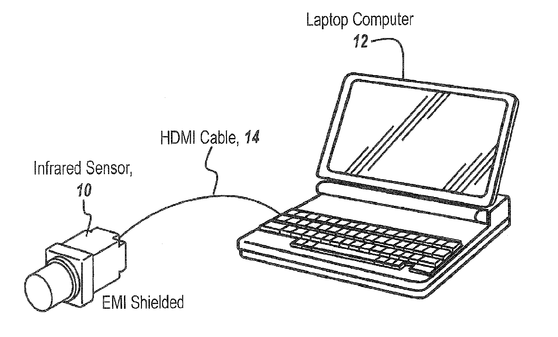
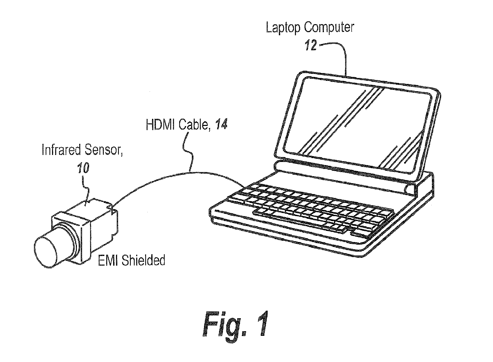
One of the problems with infrared sensors is the amount of electromagnetic interference which presents itself when an infrared camera is used to drive a conventional display, such as a laptop display.
Moreover, the type of infrared e

Method used


Image

  • High definition thermal imaging for medical applications
  • High definition thermal imaging for medical applications
  • High definition thermal imaging for medical applications

Examples


example 1

ction

[0056]FIG. 8 is an example of high resolution long wave IR output for vein detection. Referring to FIG. 8, the following comparison images demonstrate significantly more pronounced venous structure of the arm with LWIR imaging over visible imagery. By comparison of the visible image 40 with the unprocessed image 42 and the processed image 44, it can be seen how little evidence exists of vein presence when viewed by the visible eye. “Unprocessed” images refer to raw or original IR output from the FPA sensor. “Processed” images refer to the same original IR output except with real time image enhancement using the software resident on the laptop controller.

example 2

e Detection

[0057]FIG. 9 is an example of high resolution long wave IR output for hemorrhage detection. Referring to FIG. 9 and during knee cap surgery, accidental nicking of blood vessels sometimes can occur. This causes the procedure to stop and the surgeon to have to irrigate the treatment, cauterize and restart the procedure. Using high resolution IR imagery, the procedure can be shortened due to increased visibility of the damaged blood vessel area as illustrated in unprocessed form at 50 and processed form at 52.

example 3

rring Heat

[0058]FIG. 10 is an example of high resolution long wave IR output for bone temperature monitoring. Referring to FIG. 10, the same can be said for bone marrow temperature monitoring as shown at 54 for the unprocessed image and at 56 for the processed image. Note the increased image quality of the IR image after image enhancement. Note also that bone temperature rises sharply in a deburring procedure as can be seen in the thermal image in FIG. 10. The monitoring of potentially damaging excessive bone heating is possible through the use of the subject LWIR thermal imaging camera with image processing.

[0059]By way of further description and referring to FIGS. 11-14, in one embodiment of the present invention, medical thermal image processing for vein, bone, or other subsurface element detection is accomplished by using a special band-pass and scene-based noise suppression filtering, pedestal subtraction, and thermal fusion image processing system. While prior art solutions ap...


PUM


Abstract

An apparatus for high resolution thermal imaging in medical applications has a single channel EMI shielded sensor, remote cable, and laptop controller with real time image processing software. The apparatus provides high resolution, real-time viewable infrared (IR) images with a variable focus distance adjustable from six inches to infinity. The present invention enables crisp, clear imagery of the thermal band for greater awareness of everything within the field of view. Various medical applications which would benefit from high resolution thermal imagery are presented.

Description

CROSS-REFERENCE TO RELATED APPLICATIONS[0001]This Application claims rights under 35 USC §119(e) from U.S. Application Ser. No. 62 / 072,557 filed Oct. 30, 2014 the contents of which are incorporated herein by reference.[0002]This application is related to the following applications, the contents of which are incorporated hereby by reference.[0003]U.S. application Ser. No. 13 / 948,526 filed Jul. 23, 2013 entitled “CORRELATED CONTROL FOR CLOSE FOCUS STEREOSCOPIC VIEWING”,[0004]PCT application PCT / US2014 / 060897 filed Oct. 16, 2014 entitled “MEDICAL THERMAL IMAGE PROCESSING FOR SUBCUTANEOUS DETECTION OF VEINS, BONES AND THE LIKE”,[0005]U.S. application 62 / 046,195, filed Sep. 5, 2014 entitled “COMPACT MECHANISM FOR INTER-PUPIL DISTANCE ADJUSTMENT OF VIEWING SYSTEMS”, and[0006]PCT application PCT / US15 / 44195 entitled “HIGH RESOLUTION INSPECTION DEVICE FOR CASTING DEFECTS USING IR” (Docket 14-3318 PCT) filed on even date herewith.STATEMENT OF GOVERNMENT INTEREST[0007]The invention was made wi...

Claims


Application Information

Patent Timeline
IPC IPC(8): A61B5/01A61B5/00
CPCA61B5/015A61B5/489A61B5/0077A61B2562/18A61B5/725A61B5/442A61B5/445A61B5/7217A61B5/7203A61B5/02042A61B5/4504A61B2576/00G16H30/40
Inventor FRANZINI, JOHN R.LYLES, MARK B.MURPHY, ROBERT H.
Owner BAE SYST INFORMATION & ELECTRONICS SYST INTERGRATION INC
Why Eureka
Try Eureka