An assembly to control or govern relative speed of movement between parts

a technology of relative speed and movement speed, which is applied in the direction of dynamo-electric components, dynamo-electric machines, amusements, etc., can solve the problems of not providing a continuous eddy current generation path, moving parts in mechanical assemblies generally require more maintenance, and hence cost more, so as to increase the mechanical durability of the assembly, the effect of reducing the number of parts and increasing the complexity

Active Publication Date: 2016-11-03
EDDY CURRENT PARTNERSHIP
View PDF2 Cites 25 Cited by
  • Summary
  • Abstract
  • Description
  • Claims
  • Application Information

AI Technical Summary

Benefits of technology

[0006]Described herein is an assembly and methods of use thereof for controlling or governing the relative speed of motion between the assembly parts via eddy current formation. The assembly and methods may also minimise the number of parts required and may minimise the number of moving parts thereby increasing the mechanical durability of the assembly compared to art designs that may have more moving parts and greater complexity.

Problems solved by technology

This device is widely used however requires a number of moving parts.
Another disadvantage is that, when the rotors move outwards and the field is generated, the magnetic field is not continuous around the circumference of the spin axis hence does not provide a continuous eddy current generation path.
In addition, moving parts in mechanical assemblies generally require more maintenance and hence cost more.
The assembly and methods may also minimise the number of parts required and may minimise the number of moving parts thereby increasing the mechanical durability of the assembly compared to art designs that may have more moving parts and greater complexity.

Method used


Image

  • An assembly to control or govern relative speed of movement between parts
  • An assembly to control or govern relative speed of movement between parts
  • An assembly to control or govern relative speed of movement between parts

Examples


working examples

[0092]The above described assembly and methods of use are now described by reference to specific examples.

example 1

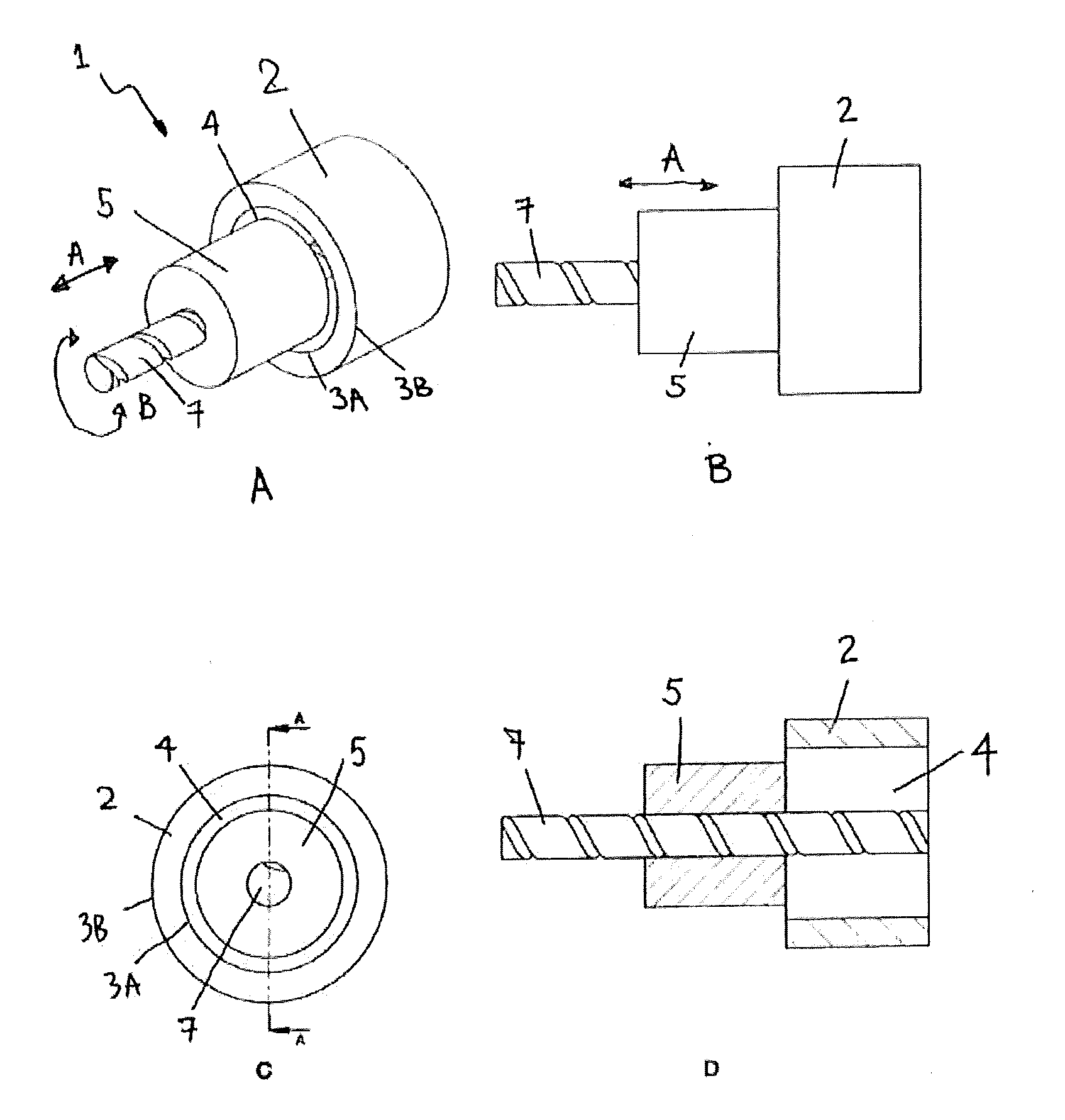
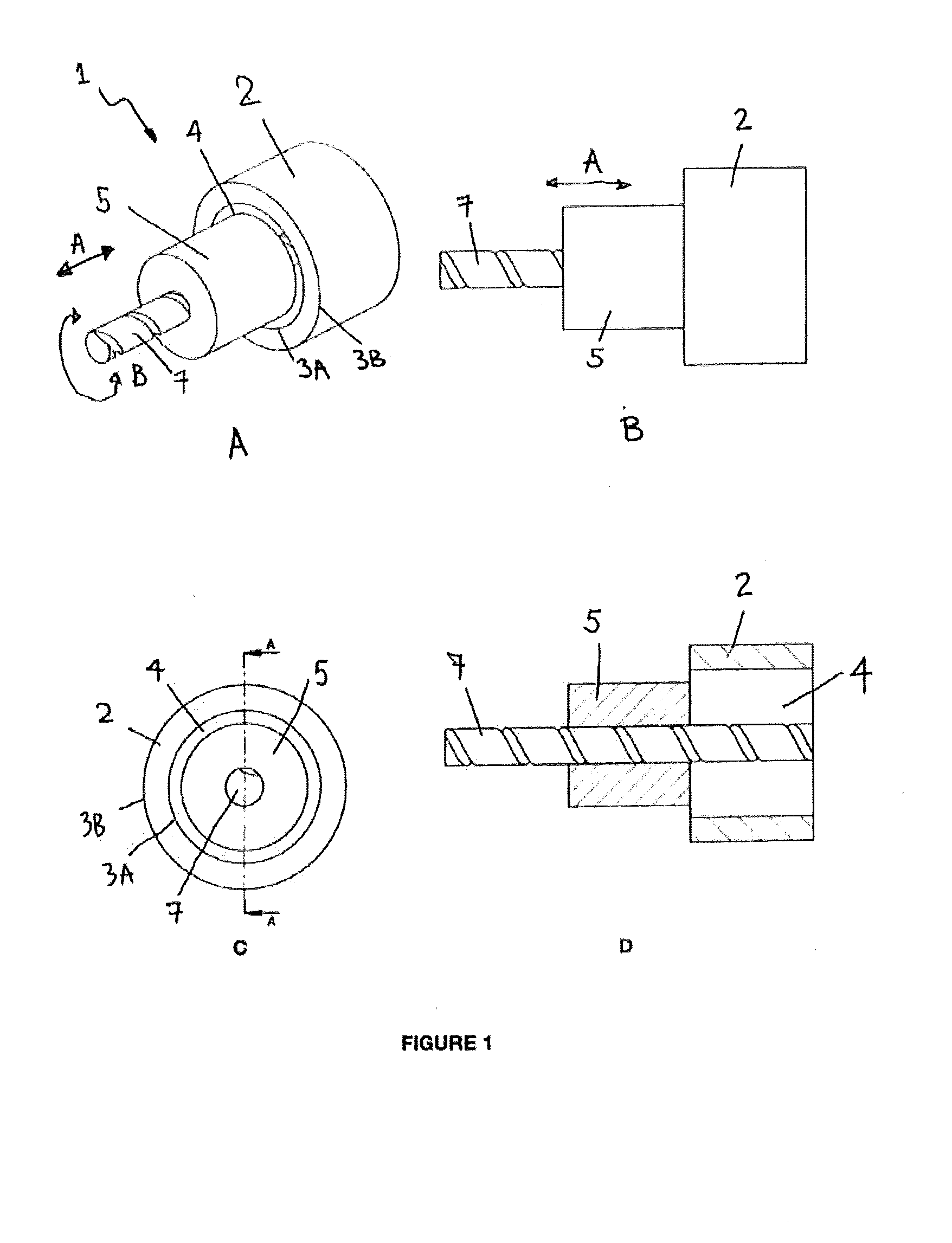
[0093]Referring to FIGS. 1A-1D, one embodiment of the assembly is shown. The assembly 1 as illustrated includes a tube 2 with an inner 3A and outer wall 3B and a void 4 therein. The assembly 1 also includes a cylinder 5. The cylinder 5 moves relative to the tube 2 via two degrees of movement being an axial translation along arrow A into and out of the tube 2 void 4 and a rotational movement B relative to tube 2. Axial movement A can be completely or partially into or out of the void 4. In the embodiment illustrated, the tube 2 and cylinder 5 share a common central axis of rotation. The cylinder 5 may rotate in direction B about a shaft 7. The shaft 7 may have a helical groove thereon which, when the shaft 7 rotates in direction B, drives axial movement A of the cylinder 5 relative to the tube 2. The tube 2 and cylinder 5 may include one or more conductive members and magnetic members (not shown). In one embodiment, the conductive member(s) may be on the tube 2 or the tube 2 it self ...

example 2

[0105]A multilayer wall approach may also be used.

[0106]As shown in FIGS. 11 to 13, the cylinder 50 is hollow 51 and mates with a tube 60 that has a complimentary hollow 61. The overlapping walls 52, 62 of the cylinder and tube may contain magnets and / or conductive members that allow variation in eddy current tuning to occur. FIGS. 11 and 12 illustrate a multilayer tube 60 nesting with a hollowed cylinder 50 and two alternate magnet 63 configurations on the tube walls 62. FIG. 13 illustrates a multiwall 52, 62 approach where both tube 60 and cylinder 50 have multiple concentric walls 52, 62 that mate together.


PUM


Abstract

Described herein is an assembly and methods of use thereof for controlling or governing the relative speed of motion between the assembly parts via eddy current formation. The assembly and methods also may minimise the number of parts required and may minimise the number of moving parts thereby increasing the mechanical durability of the assembly compared to art designs that may have more moving parts and greater part complexity.

Description

TECHNICAL FIELD[0001]Described herein is an assembly to control or govern relative speed of movement between parts. More specifically, described herein is an assembly that uses eddy current formation to control or govern the relative speed of movement between two parts.BACKGROUND ART[0002]Eddy current formation may be used in a variety of ways to adjust the speed of rotation of a member. Various apparatus exist, for example in abseiling, to control the descent of a climber or for example, in personal protective equipment scenarios to prevent an injury causing fall. Other applications that use eddy current generation are in controlling payout of line in trains, cable cars, zip line devices and roller coasters.[0003]One art device is published as US2012 / 0055740. This device utilises a rotor assembly. The rotors themselves may be conductive or magnetic or may have conductive or magnetic members attached thereto. When a rotational force is applied, the rotors move outwards from a centra...

Claims


Application Information

Patent Timeline
Patent Type & Authority Applications(United States)
IPC IPC(8): A63G21/20A62B35/00
CPCA62B35/0093A63G21/20H02K49/043H02K2213/03A62B1/06
Inventor DIEHL, ANDREW KARLWRIGHT, KEVIN A.
Owner EDDY CURRENT PARTNERSHIP
Why Eureka
Try Eureka