
Method and device for obtaining measurements of downhole properties in a subterranean well

Inactive Publication Date: 2016-11-03
SAUDI ARABIAN OIL CO
View PDF7 Cites 43 Cited by
  • Summary
  • Abstract
  • Description
  • Claims
  • Application Information

AI Technical Summary

Benefits of technology

The patent describes a system for controlling the location of an untethered device in a well using buoyancy and drag. This allows for more efficient and cost-effective locomotion in the well compared to conventional tools. The system includes a controller that can adjust the drag of the device using a fin to ensure accurate measurements of downhole properties in the well. This technology provides faster and easier logistical and operational delays and reduces costs compared to conventional tools.

Problems solved by technology

Conventional tethered logging tools and the cable or wiring attached thereto are generally bulky, requiring specialized vehicles or equipment and a specialized crew of technicians to deploy and operate.
The need to mobilize specialized vehicles and / or other large equipment and to provide a crew of technicians to remote well sites increases the expense associated with well logging and can introduce undesirable delays in obtaining needed data.
Recorded data from these sensors is generally limited, however, to temperature, pressure or strain, and acoustic data.
The cost of deploying such a network of wired measurement devices can be significant, and well operation must be stopped and taken off-line to deploy the long downhole cables.
However, there is no tether length which can be measured at the surface to determine where along the trajectory of the well the untethered measurements were taken.

Method used


Image

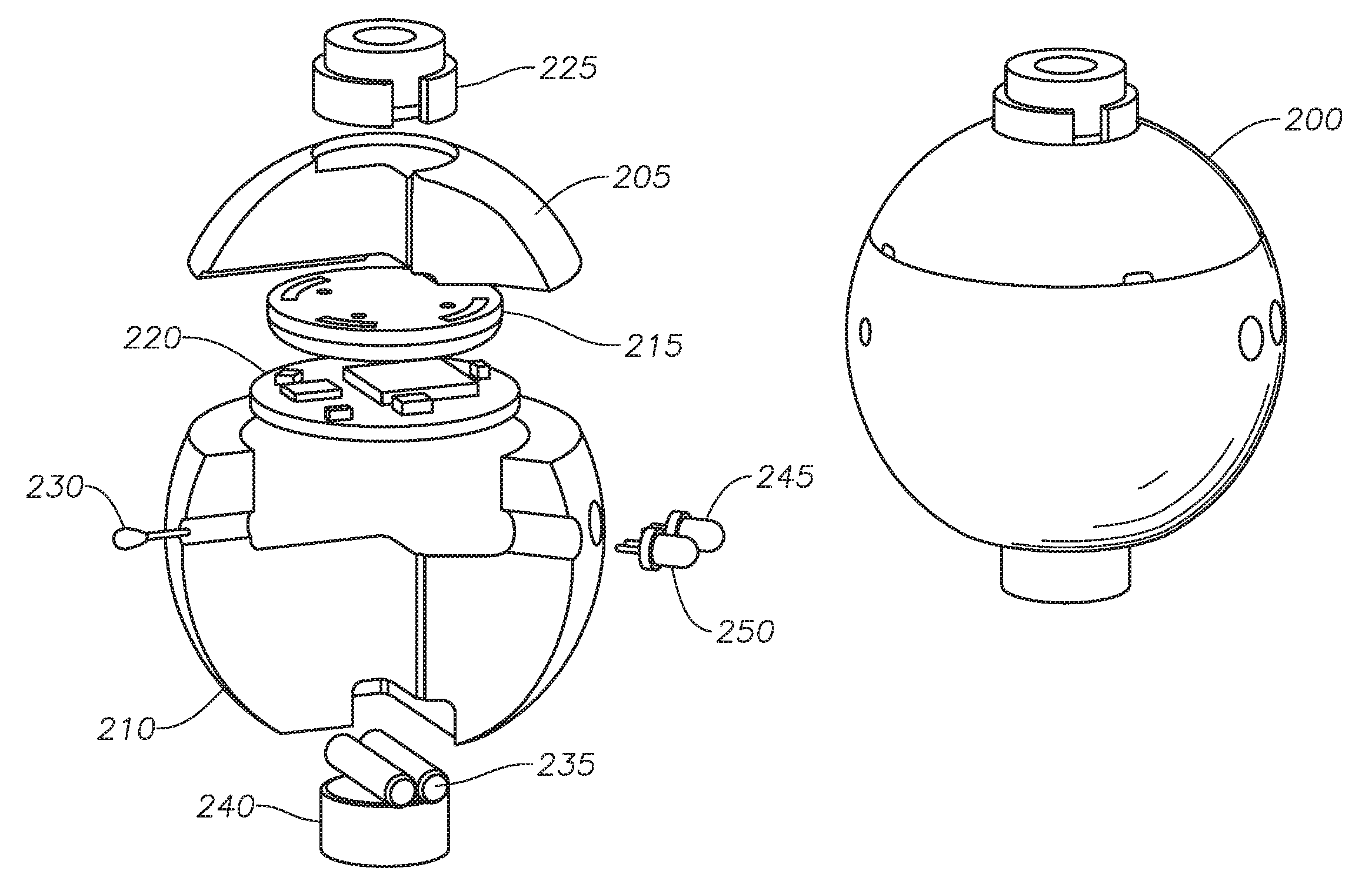
  • Method and device for obtaining measurements of downhole properties in a subterranean well
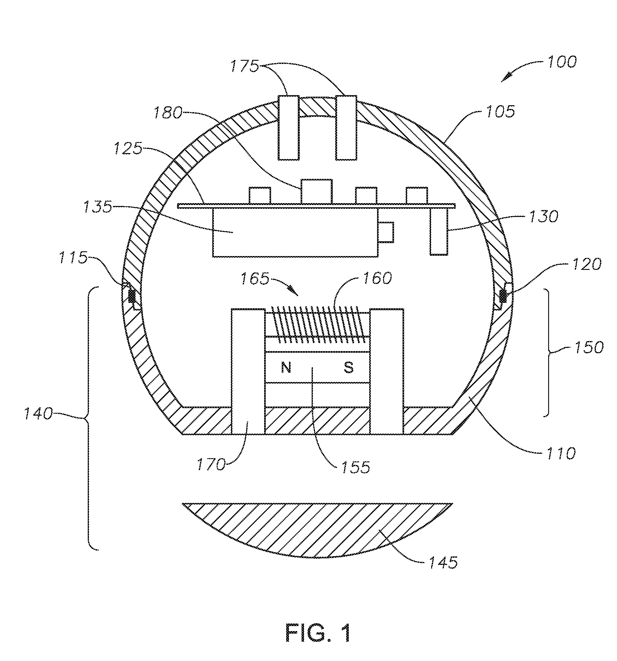
  • Method and device for obtaining measurements of downhole properties in a subterranean well
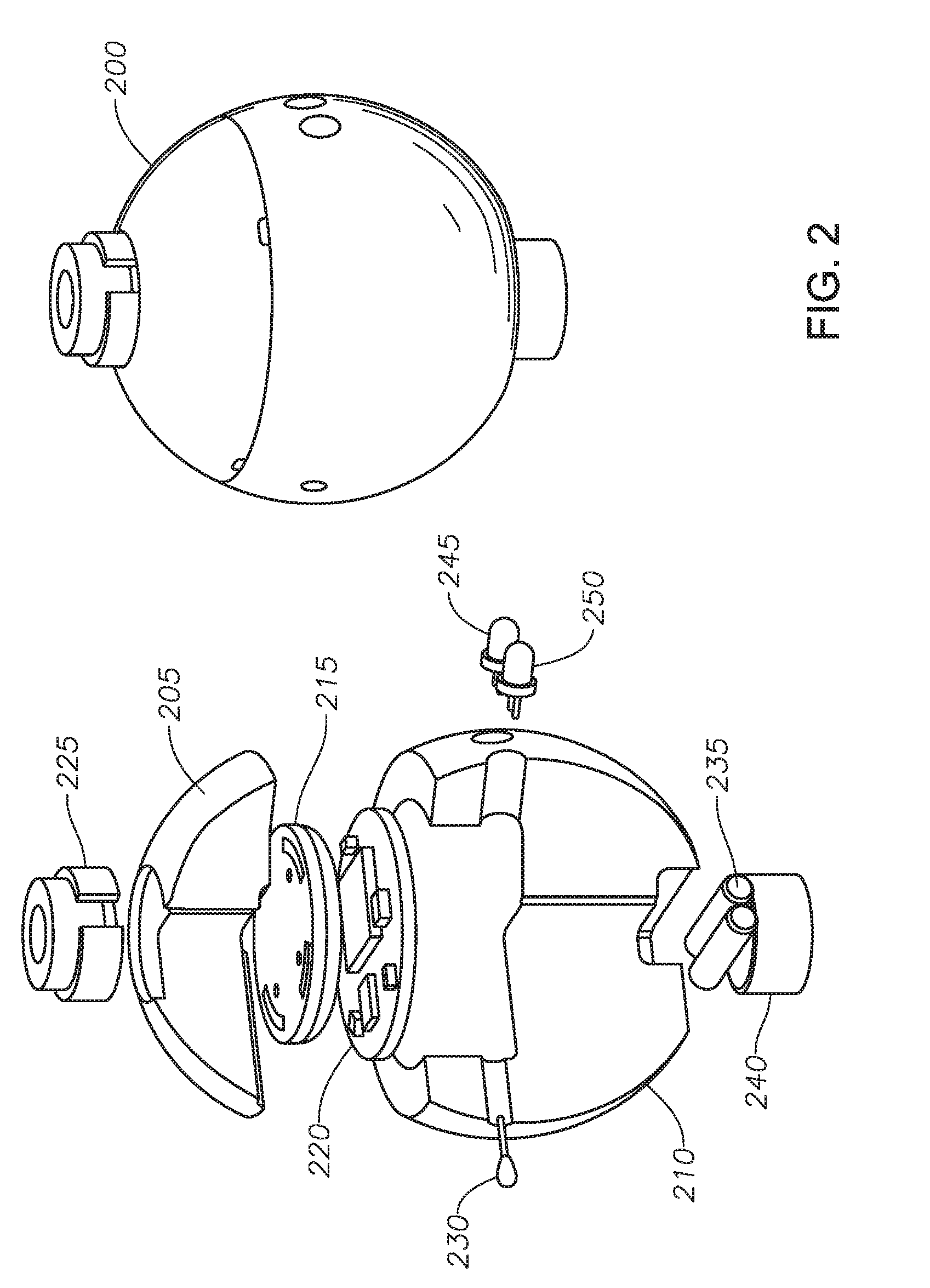
  • Method and device for obtaining measurements of downhole properties in a subterranean well

Examples


Embodiment Construction

[0040]Advantages and features of the present invention and methods of accomplishing the same will be apparent by referring to embodiments described below in detail in connection with the accompanying drawings. However, the present invention is not limited to the embodiments disclosed below and may be implemented in various different forms. The embodiments are provided only for completing the disclosure of the present invention and for fully representing the scope of the present invention to those skilled in the art.

[0041]For simplicity and clarity of illustration, the drawing figures illustrate the general manner of construction, and descriptions and details of well-known features and techniques may be omitted to avoid unnecessarily obscuring the discussion of the described embodiments of the invention. Additionally, elements in the drawing figures are not necessarily drawn to scale. For example, the dimensions of some of the elements in the figures may be exaggerated relative to ot...


PUM


Abstract

Embodiments of the invention provide an untethered apparatus for measuring properties along a subterranean well. According to at least one embodiment, the untethered apparatus includes a housing, and one or more sensors configured to measure data along the subterranean well. The data includes one or more physical, chemical, geological or structural properties in the subterranean well. The untethered apparatus further includes a processor configured to control the one or more sensors measuring the data and to store the measured data, and a transmitter configured to transmit the measured data to a receiver arranged external to the subterranean well. Further, the untethered apparatus includes a controller configured to control the buoyancy or the drag of the untethered apparatus to control a position of the untethered apparatus in the subterranean well. The processor includes instructions defining measurement parameters for the one or more sensors of the untethered apparatus within the subterranean well.

Description

CROSS REFERENCE TO RELATED APPLICATIONS[0001]This application claims the benefit of and priority to U.S. Provisional Patent Application Ser. No. 62 / 155,219, filed on Apr. 30, 2015, entitled, “METHOD AND DEVICE FOR OBTAINING MEASUREMENTS OF DOWNHOLE PROPERTIES IN A SUBTERRANEAN WELL,” which is hereby incorporated by reference in its entirety into this application.BACKGROUND[0002]1. Field of the Invention[0003]Embodiments of the present invention generally relate to a method and device for obtaining measurements of downhole properties along a subterranean well. More particularly, embodiments of the present invention relate to an untethered, buoyancy-controlled and / or drag-controlled device and a method of use of the device for measuring physical, chemical, geological, and structural properties along a well.[0004]2. Description of the Related Art[0005]Measurement of downhole properties along a subterranean well is critical to the drilling, completion, operation, and abandonment of well...

Claims


Application Information

Patent Timeline
IPC IPC(8): G05B19/406E21B47/09E21B47/12E21B47/06
CPCG05B19/406E21B47/06E21B47/09E21B47/124G05B2219/36292E21B47/091E21B47/065E21B47/123E21B47/122E21B47/10E21B47/26E21B47/138E21B23/10E21B47/04E21B47/095E21B47/07E21B47/135E21B47/113E21B47/114E21B47/13E21B47/12
Inventor DEFFENBAUGH, MAXHAM, GREGORY D.ALVAREZ, JOSE OLIVERIOBERNERO, GREGORYRAMACHANDRAN, SUNDERGONZALEZ, MIGUELCSUTAK, SEBASTIANPOWELL, CHRISTOPHERSEREN, HUSEYIN
Owner SAUDI ARABIAN OIL CO
Learn More