Endoscopic camera head
a camera head and endoscopic technology, applied in the field of endoscopic camera heads, can solve the problems that none of the proposed methods so far adequately reduce flare and ghosting, and achieve the effects of improving the quality of the captured image, reducing flare and ghosting, and capturing a higher quality imag
- Summary
- Abstract
- Description
- Claims
- Application Information
AI Technical Summary
Benefits of technology
Problems solved by technology
Method used
Image
Examples
first embodiment
2. First Embodiment
2-1. Configuration of Endoscopic Device
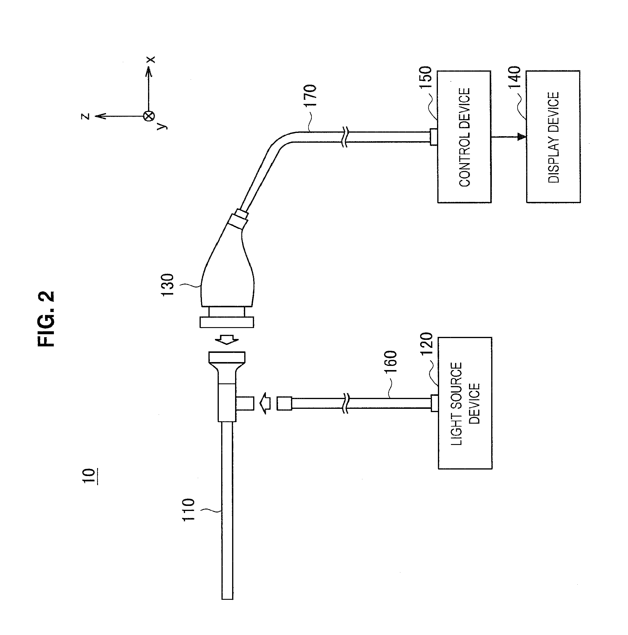
[0061]A configuration of an endoscopic device according to the first embodiment of the present disclosure will be described with reference to FIG. 2. FIG. 2 is a diagram illustrating an example configuration of an endoscopic device according to the first embodiment.
[0062]Referring to FIG. 2, the endoscopic device 10 according to the first embodiment primarily includes an endoscope 110, a light source device 120, a camera head 130, a display device 140, and a control device 150.
[0063]The endoscope 110 is a rigid scope having a narrow insertion unit, and at the tip of the insertion unit, an illumination window that shines illuminating light onto a target of observation and an observation window that captures light (that is, observation light) reflected from the target of observation due to the illuminating light are provided. When capturing an image, the insertion unit of the endoscope 110 is inserted inside a patient's body ca...
second embodiment
3. Second Embodiment
[0095]A second embodiment of the present disclosure will now be described. Note that the second embodiment corresponds to a modification of the configuration of the image sensor 211 in the first embodiment described above. The configuration of the endoscopic device and the configuration of parts of the optical system other than the image sensor are similar to the first embodiment, and thus in the following description of the second embodiment, detailed description of items overlapping with the first embodiment will be reduced or omitted, and items differing from the first embodiment will be described primarily.
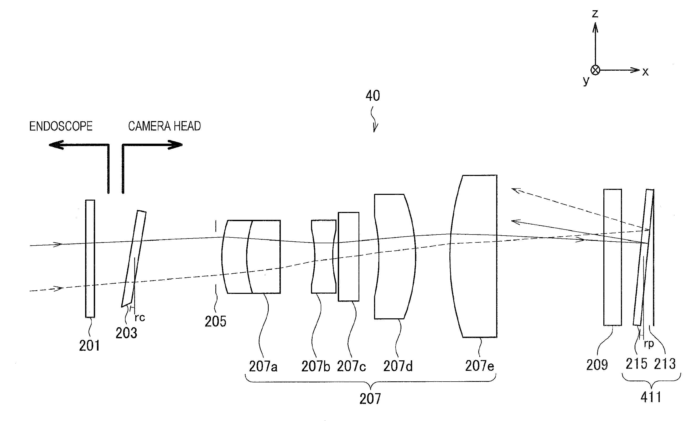
[0096]A configuration of the optical system according to the second embodiment will be described with reference to FIG. 4. FIG. 4 is a diagram illustrating an example configuration of the optical system according to the second embodiment. The optical system illustrated in FIG. 4 corresponds to an optical system made up of the various optical members existin...
third embodiment
4. Third Embodiment
[0110]A third embodiment of the present disclosure will now be described. Note that the third embodiment corresponds to a modification of the configuration of the cover glass 203 and the configuration of the image sensor 211 in the first embodiment described above. The configuration of the endoscopic device and the configuration of parts of the optical system other than the cover glass and the image sensor are similar to the first embodiment, and thus in the following description of the third embodiment, detailed description of items overlapping with the first embodiment will be reduced or omitted, and items differing from the first embodiment will be described primarily.
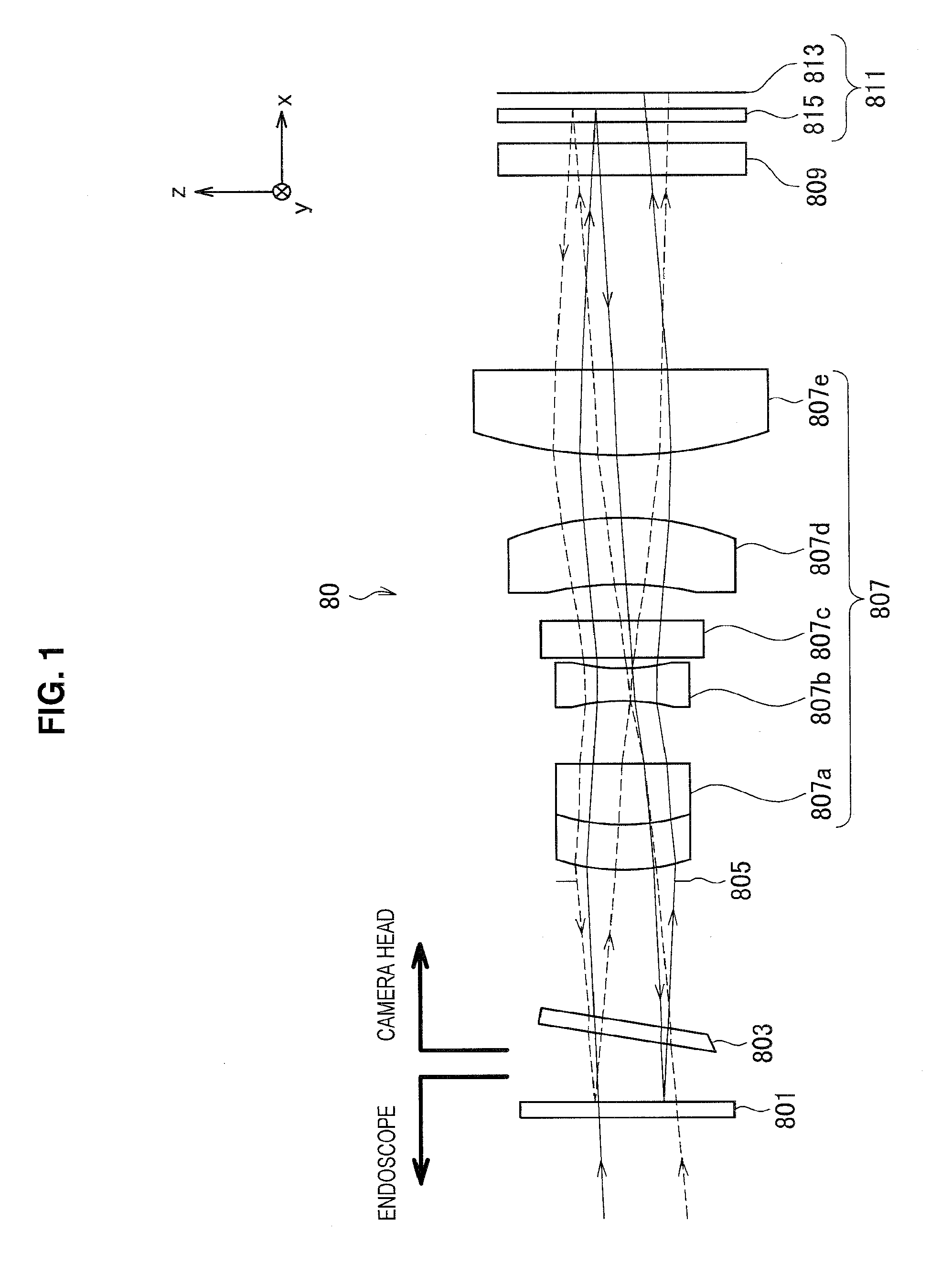
[0111]A configuration of the optical system according to the third embodiment will be described with reference to FIG. 6. FIG. 6 is a diagram illustrating an example configuration of an optical system according to the third embodiment. The optical system illustrated in FIG. 6 corresponds to an opt...
PUM
| Property | Measurement | Unit |
|---|---|---|
| distance dpg | aaaaa | aaaaa |
| distance dpg | aaaaa | aaaaa |
| distance dpg | aaaaa | aaaaa |
Abstract
Description
Claims
Application Information
 - R&D
- Intellectual Property
- Life Sciences
- Materials
- Tech Scout
- Unparalleled Data Quality
- Higher Quality Content
- 60% Fewer Hallucinations
Browse by: Latest US Patents, China's latest patents, Technical Efficacy Thesaurus, Application Domain, Technology Topic, Popular Technical Reports.
© 2025 PatSnap. All rights reserved.Legal|Privacy policy|Modern Slavery Act Transparency Statement|Sitemap|About US| Contact US: help@patsnap.com


