Three-dimensional image display device and driving method thereof

a three-dimensional image and display device technology, applied in the direction of steroscopic systems, electrical devices,pictoral communication, etc., can solve the problems of crosstalk in misalignment between the display panel and the viewpoint divider, etc., to improve the yield of the three-dimensional image display device, reduce the error of optical bonding, and remove crosstalk

Inactive Publication Date: 2016-11-03
SAMSUNG DISPLAY CO LTD
View PDF8 Cites 11 Cited by
  • Summary
  • Abstract
  • Description
  • Claims
  • Application Information

AI Technical Summary

Benefits of technology

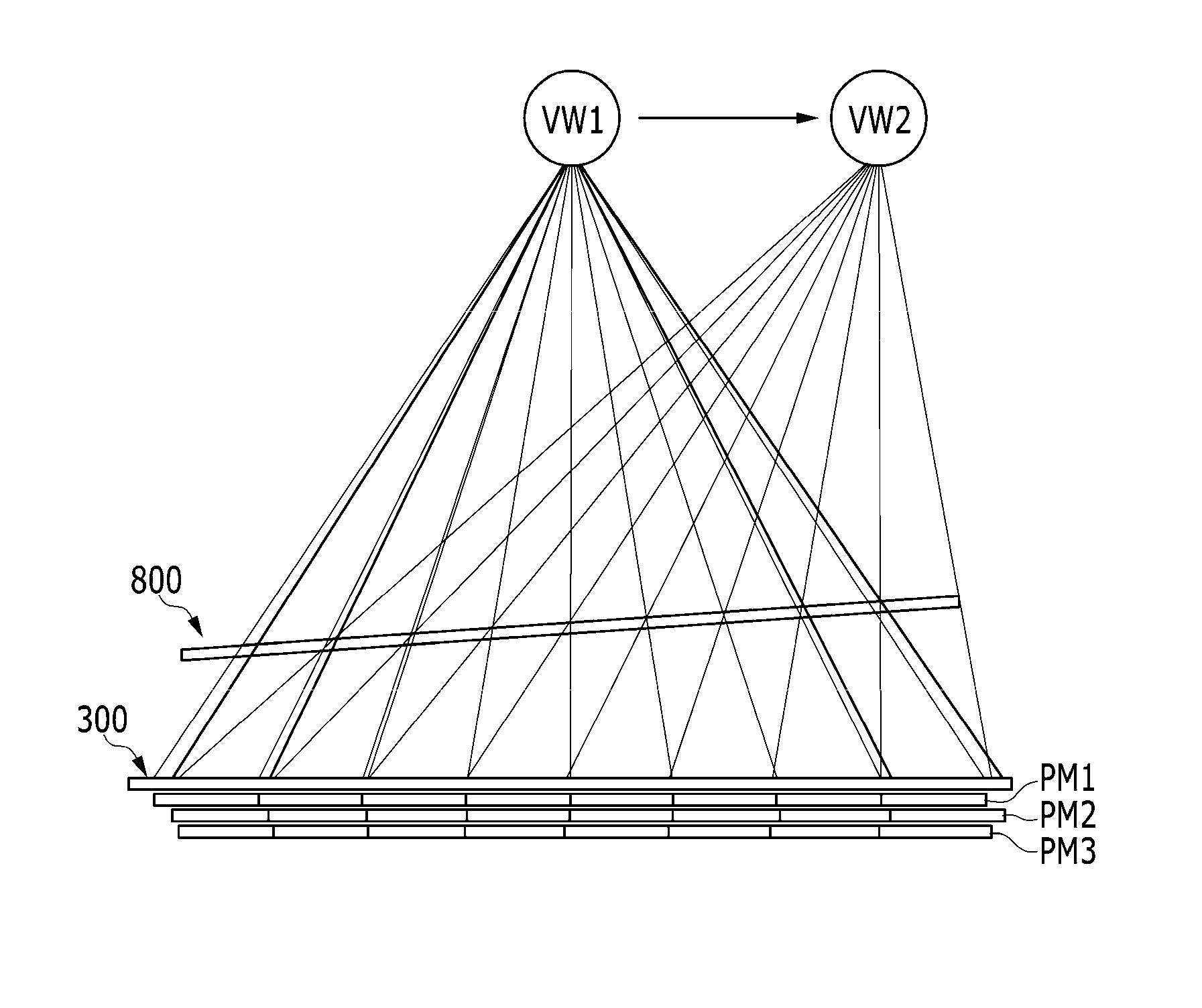
[0029]In accordance with the three-dimensional image display device according to an exemplary embodiment of the present disclosure, it is possible to compensate for the misalignment between the display panel and the viewpoint divider and remove the crosstalk due to the misalignment between the display panel and the viewpoint divider.
[0030]Further, it is possible to increase the permissible error of the optical bonding between the display panel and the viewpoint divider and improve the yield of the three-dimensional image display device by compensating for the misalignment occurring while the display panel is bonded to the viewpoint divider by the driving method of the three-dimensional image display device.
[0031]In addition, it is possible to remove the additional compensation circuit in the driving board for displaying the three-dimensional image by storing the parameters for the alignment between the display panel and the viewpoint divider in the storage unit and performing the actual compensation processing in the image processing application.

Problems solved by technology

However, a misalignment in which the display panel and the viewpoint divider are not accurately bonded to each other, as designed, may occur during the bonding process.
The misalignment may cause a crosstalk in the three-dimensional image display device.

Method used


Image

  • Three-dimensional image display device and driving method thereof
  • Three-dimensional image display device and driving method thereof
  • Three-dimensional image display device and driving method thereof

Examples


Embodiment Construction

[0040]Hereinafter, the present system and method are described more fully with reference to the accompanying drawings in which exemplary embodiments of the present system and method are shown. As those skilled in the art would realize, the described embodiments may be modified in various different ways, all without departing from the spirit or scope of the present disclosure.

[0041]Further, in exemplary embodiments, since like reference numerals designate like elements having the same configuration, a first exemplary embodiment is representatively described, and in other exemplary embodiments, only a configuration different from the first exemplary embodiment is described.

[0042]Accordingly, the drawings and description are to be regarded as illustrative in nature and not restrictive. Like reference numerals designate like elements throughout the specification.

[0043]Throughout this specification and the claims that follow, when it is described that an element is “coupled” to another e...


PUM


Abstract

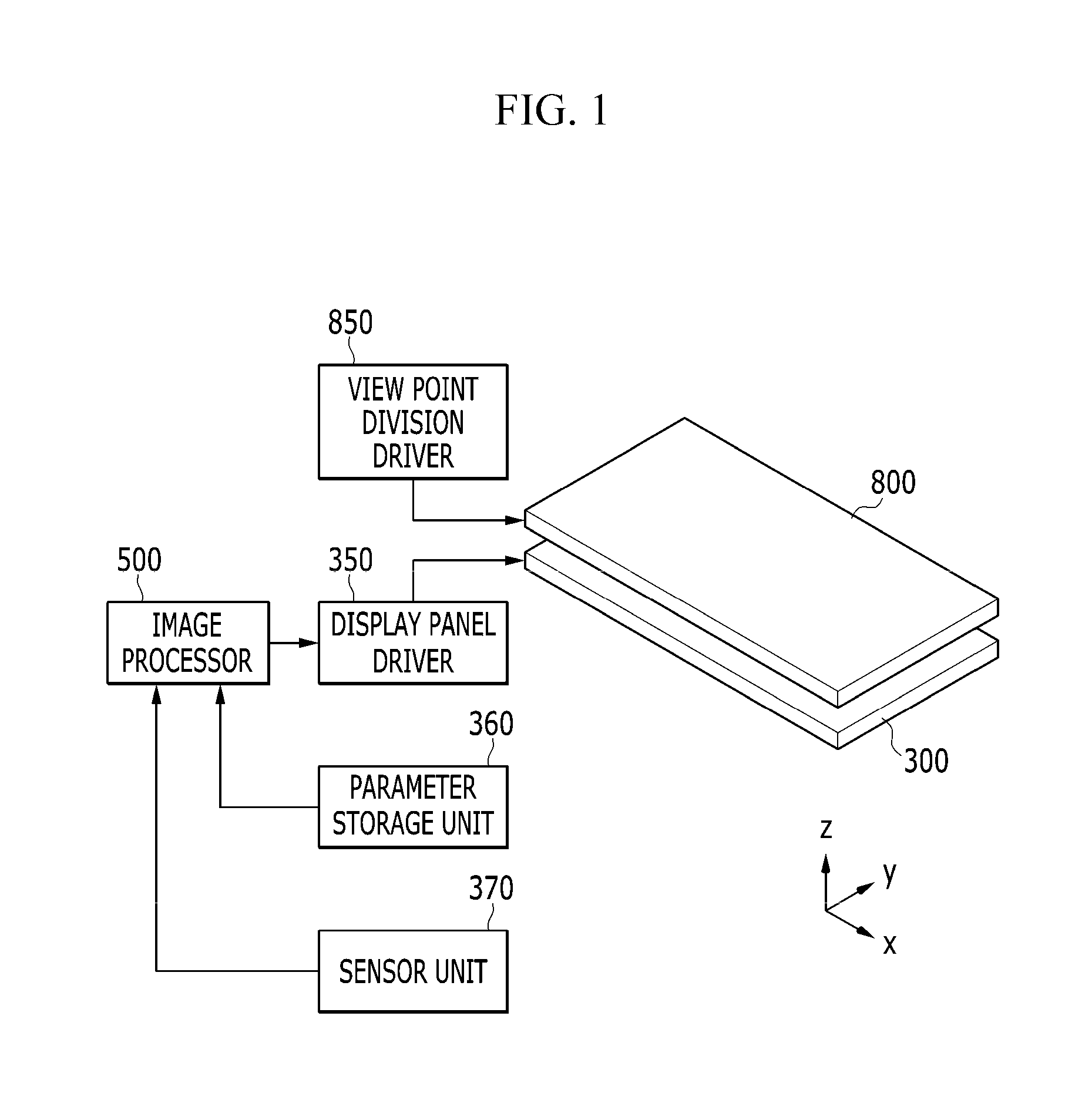
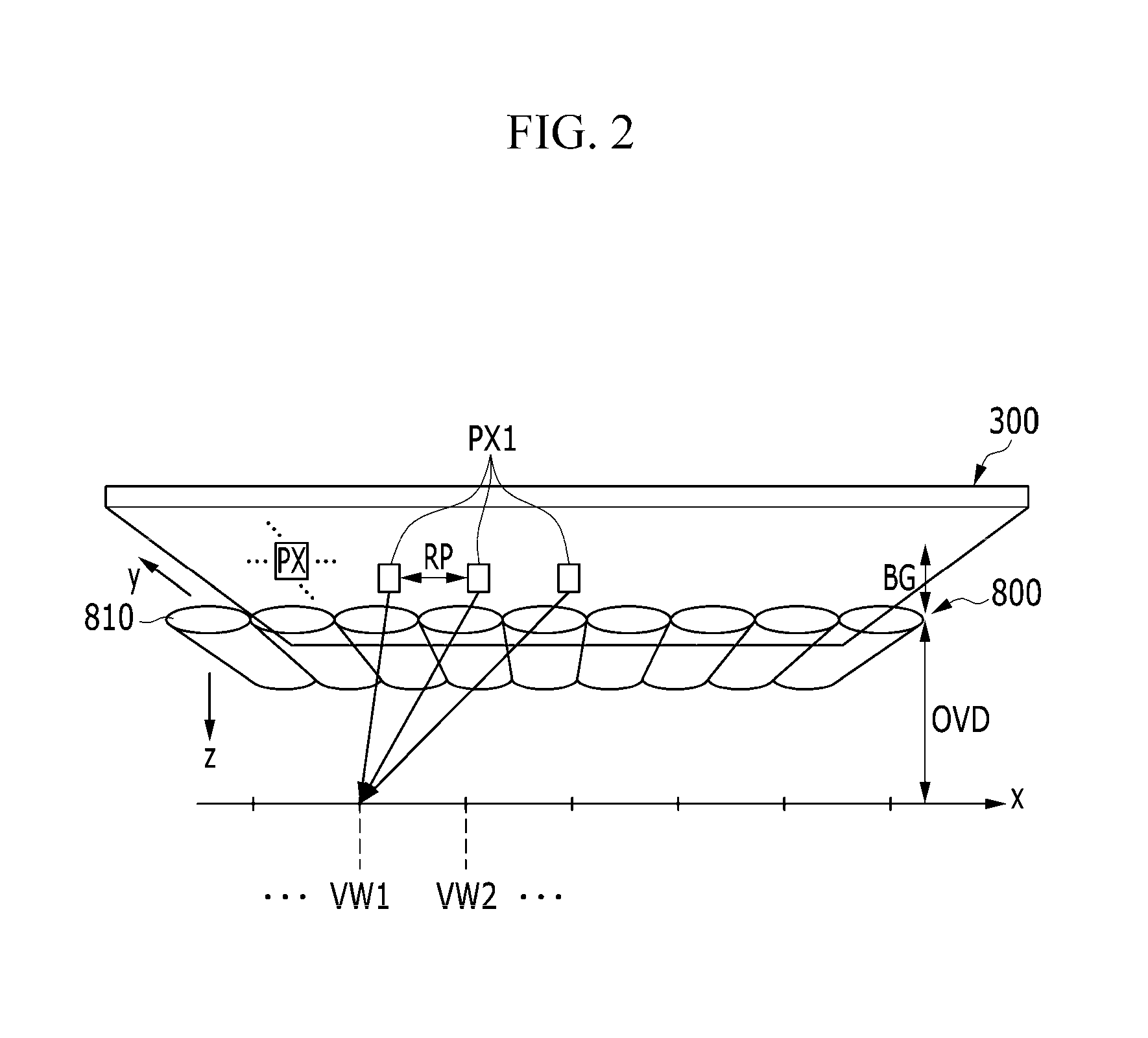
There is provided a three-dimensional image display device, including: a display panel including a plurality of signal lines and a plurality of pixels connected to the plurality of signal lines; a viewpoint divider configured to divide an image displayed by the display panel into a plurality of viewpoints; a parameter storage unit configured to store parameters for an alignment between the display panel and the viewpoint divider; an image processor configured to calculate a rendering pitch according to the alignment between the display panel and the viewpoint divider by using the parameters stored in the parameter storage unit and generate an image signal to perform pixel mapping according to the rendering pitch; and a display panel driver configured to receive the image signal to drive the display panel.

Description

CROSS-REFERENCE TO RELATED APPLICATION[0001]This application claims priority to and the benefit of Korean Patent Application No. 10-2015-0060001 filed in the Korean Intellectual Property Office on Apr. 28, 2015, the entire contents of which are incorporated herein by reference.BACKGROUND[0002](a) Field[0003]The present disclosure relates to a three-dimensional image display device and a driving method thereof, and more particularly, to a three-dimensional image display device and a driving method thereof capable of compensating for misalignment between a display panel and a viewpoint divider.[0004](b) Description of the Related Art[0005]Generally, a stereoscopic image in a three-dimensional (3D) display is implemented based on a principle of stereo vision by two eyes, called binocular disparity. Binocular disparity between two eyes occurs due to the two eyes being spaced apart from each other, as much as about 65 mm, and is the basis for generating a three-dimensional effect. Partic...

Claims


Application Information

Patent Timeline
Patent Type & Authority Applications(United States)
IPC IPC(8): H04N13/04H04N13/00
CPCH04N13/0497H04N13/0007H04N13/0484H04N13/0404H04N13/0425H04N13/0422H04N13/31H04N13/317H04N13/305H04N13/327H04N13/398
Inventor KIM, TAE HYUNGKIM, KANG-MINSUNG, JEONG MINYIM, HYUNG WOOJANG, HYEON YONG
Owner SAMSUNG DISPLAY CO LTD
Why Eureka
Try Eureka