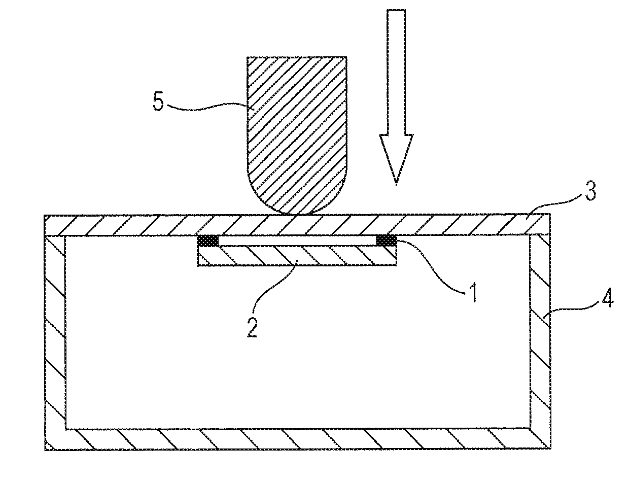
Adhesive tape and electronic apparatus

a technology of adhesive tape and electronic equipment, applied in the field of adhesive tape, can solve the problems of inability to transmit vibration, give the operator a handshake, and the operation of electronic equipment, and achieve the effects of improving the impact resistance, and small displacemen

Inactive Publication Date: 2016-11-10
DAINIPPON INK & CHEM INC
View PDF0 Cites 9 Cited by
  • Summary
  • Abstract
  • Description
  • Claims
  • Application Information

AI Technical Summary

Benefits of technology

[0019]An adhesive tape of the present invention has a so-called touch feedback characteristic that very small displacement (compression) can be produced corresponding to a very small pushing-in amount of a touch panel portion and transmission of vibration to the touch panel portion and a fingertip is not inhibited, and thus the adhesive tape can be manly used for fixing a casing and a touch panel device having a touch feedback function.
[0020]Also, the adhesive tape of the present invention is excellent in the touch feedback characteristic, impact resistance, followability to irregularities of a surface of an adherend, and peeling resistance, and thus can be preferably used for manufacturing a portable electronic device which is liable to be dropped, particularly a portable electronic device such as a smartphone, a tablet computer, a notebook computer, or a game machine, which is highly requested to have impact resistance with increasing screen sizes.

Problems solved by technology

However, beginners and elderly persons never having used the electronic apparatuses are often inexperienced in touch-panel operation and may cause an error in operation of the electronic apparatuses.
However, an adhesive tape generally used for fixing a touch panel portion and a casing does not have the characteristic of being slightly displaced (compressed) in corresponding to push-in displacement of the touch panel portion when the surface of the touch panel portion is slightly pushed in, and thus vibration or the like corresponding to the pushing-in may not be given to the operator.
Although the vibration or the like generated by sensing the pushing-in is transmitted to a fingertip as well as the touch panel portion through the adhesive tape, the usual adhesive tape has a problem that transmission of the vibration may be inhibited, or the vibration is transmitted to the side (the casing side) opposite to the touch panel portion.
The adhesive tape is required to be further thinned with thinning and miniaturization of the electronic apparatuses, but in a present situation, there has not yet been found a thin adhesive tape capable of very small displacement corresponding to a very small pushing-in amount of the touch panel without inhibiting the transmission of vibration to the touch panel portion and a fingertip.

Method used

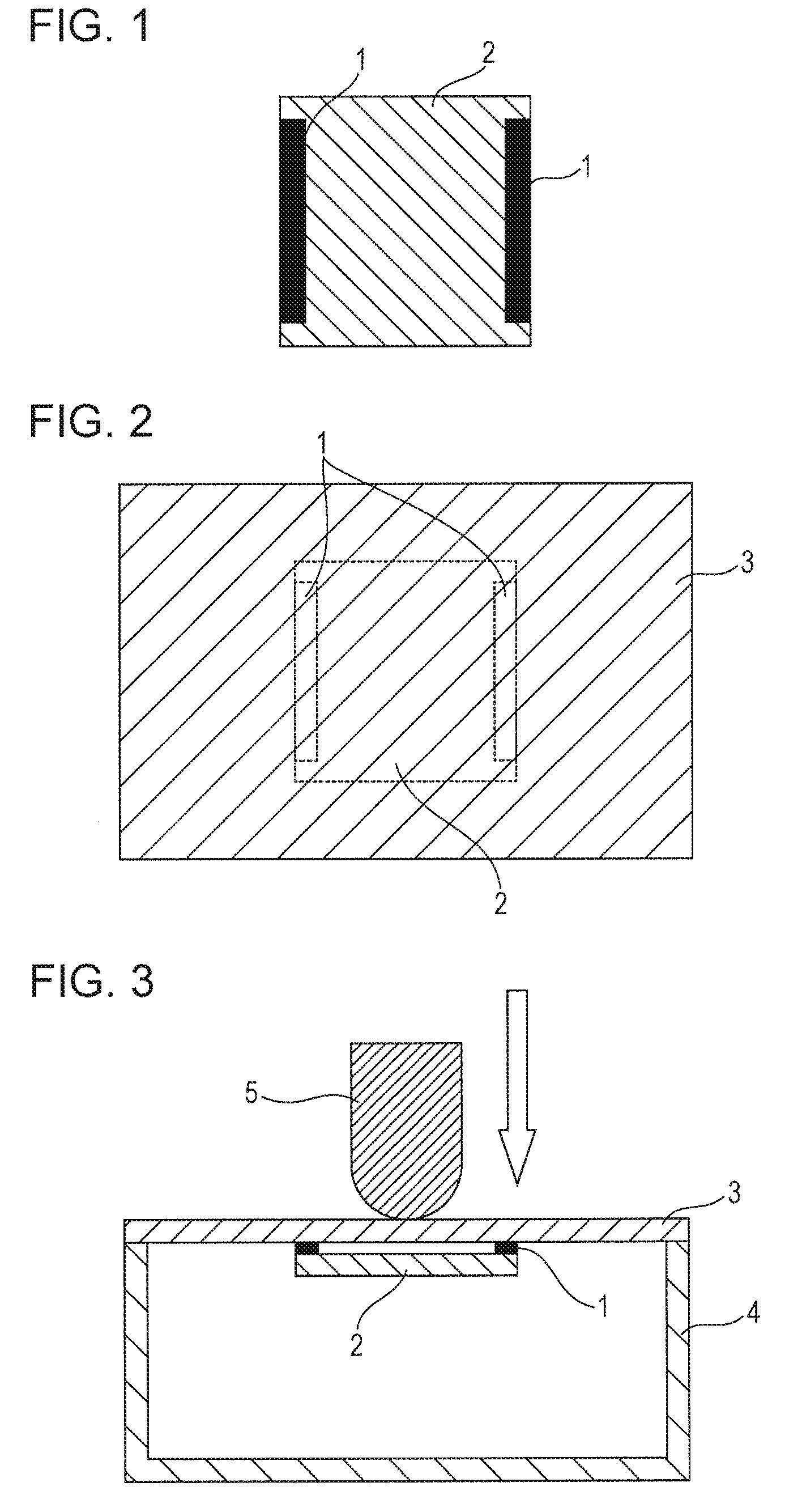

Image

  • Adhesive tape and electronic apparatus
  • Adhesive tape and electronic apparatus

Examples


example 1

Formation of Double-Sided Adhesive Tape

[0151]To 100 parts by mass of the adhesive composition (A), 1.1 parts by mass of “Coronate L-45” (manufactured by Nippon Polyurethane Industry Co., Ltd., isocyanate-based crosslinking agent, solid content 45% by mass) was added and stirred for 15 minutes, and then the resultant mixture was applied to a release-treated surface of a release-treated polyethylene terephthalate film (PET film) having a thickness of 75 μm so that the thickness after drying was 75 μm and then dried at 80° C. for 3 minutes to form an adhesive layer.

[0152]The adhesive layer formed by allowing the adhesive layer to stand (aging) in an environment of 40° C. for 48 hours had a gel fraction of 48% by mass and a temperature of −17° C. at which a peak value of loss tangent (tan δ) at a frequency of 1 Hz was exhibited.

[0153]Next, the adhesive layer before the aging was attached to each of the both surfaces of a substrate including a black polyolefin foam (1) (a foam manufactur...

example 2

[0155]A double-sided adhesive tape having a thickness of 350 μm was formed by the same method as in Example 1 except that the adhesive composition (B) was used in place of the adhesive composition (A), and 1.33 parts by mass of “Coronate L-45” (manufactured by Nippon Polyurethane Industry Co., Ltd., isocyanate-based crosslinking agent, solid content 45% by mass) was used relative to 100 parts by mass of the adhesive composition (B).

[0156]An adhesive layer formed by allowing the adhesive layer to stand (aging) in an environment of 40° C. for 48 hours had a gel fraction of 37% by mass and a temperature of 2° C. at which a peak value of loss tangent (tan δ) at a frequency of 1 Hz was exhibited.

example 3

[0157]A double-sided adhesive tape having a thickness of 350 μm was formed by the same method as in Example 1 except that the adhesive composition (C) was used in place of the adhesive composition (A), and 1.0 parts by mass of “Coronate L-45” (manufactured by Nippon Polyurethane Industry Co., Ltd., isocyanate-based crosslinking agent, solid content 45% by mass) was used relative to 100 parts by mass of the adhesive composition (C).

[0158]An adhesive layer formed by allowing the adhesive layer to stand (aging) in an environment of 40° C. for 48 hours had a gel fraction of 42% by mass and a temperature of −28° C. at which a peak value of loss tangent (tan δ) at a frequency of 1 Hz was exhibited.


PUM

PropertyMeasurementUnit
thicknessaaaaaaaaaa
thicknessaaaaaaaaaa
thicknessaaaaaaaaaa

Abstract

The present invention provides an adhesive tape capable of giving a tactile feedback when being used for fixing a component of a touch panel device having the function of sensing contact with an object and giving a tactile feedback. The present invention relates to an adhesive tape including a foam substrate layer and an adhesive layer, wherein the adhesive tape is used for fixing a touch panel device having the function of sensing contact with or approach to the touch panel device and giving tactile feedback, and when the adhesive tape is compressed in the thickness direction with a compressive load of 5 N/cm2, a displacement is 12 μm or more and less than 130 μm.

Description

TECHNICAL FIELD[0001]The present invention relates to an adhesive tape used for fixing a casing and a touch-panel device having a touch feedback function.BACKGROUND ART[0002]In recent years, small electronic apparatuses with a touch-panel function have been widely spread as those such as an electronic organizer, a cellular phone, PHS, a smartphone, a digital camera, a music player, a television, a notebook computer, a tablet computer, a game machine, a car navigation system, etc.[0003]However, beginners and elderly persons never having used the electronic apparatuses are often inexperienced in touch-panel operation and may cause an error in operation of the electronic apparatuses.[0004]A known function of preventing the operation error is a so-called touch feedback function of being capable of simply and precisely confirming whether or not an operation input to a touch panel is received by an electronic apparatus.[0005]A function investigated as the touch feedback function is, for e...

Claims


Application Information

Patent Timeline
Patent Type & Authority Applications(United States)
IPC IPC(8): C09J7/02G06F3/01G06F3/041C09J7/26
CPCC09J7/0289G06F3/041C09J2433/00C09J2203/326C09J2423/006G06F3/016C09J193/04C09J201/00C09J2203/318C09J133/08C09J7/26C09J2301/312C08F220/1804C08F220/06C08F220/20C09J133/06
Inventor IWASAKI, TAKESHITAKEI, HIDEAKIKOMATSUZAKI, YUKI
Owner DAINIPPON INK & CHEM INC
Why Eureka
Try Eureka