
Magnetic field sensing apparatus and magnetic field sensing module

a magnetic field and sensing module technology, applied in the direction of magnetic measurement, instruments, surveying and navigation, etc., can solve the problems of complex processes, difficult to reduce manufacturing costs, and differences in precision on one axes, so as to achieve simplified structure and small size

Active Publication Date: 2016-11-10
ISENTEK INC
View PDF7 Cites 13 Cited by
  • Summary
  • Abstract
  • Description
  • Claims
  • Application Information

AI Technical Summary

Benefits of technology

The invention is a magnetic field sensing apparatus that has a simplified structure and is smaller in size. It can sense magnetic field components in three directions using fewer magnetoresistance sensors. The apparatus has a simpler framework and a smaller size compared to previous designs. The direction of the magnetic field sensors can be effectively set using three spiral conductive units, making the apparatus easier to use and smaller in size. This design has improved the accuracy and efficiency of magnetic field sensing.

Problems solved by technology

However, since the sensing sensitivity of the Hall element is different from the sensing sensitivity of the GMR (or TMR) multilayer film structure, the difference may make the precision on one of the axes different from the precision on the other two axes.
Thus, when the user rotates the portable electronic apparatus to a different angle, the sensing sensitivity to the same magnetic field may become different, thus causing confusion.
The manufacturing processes are thus complicated, so it is difficult to reduce the manufacturing cost.
Moreover, such manufacturing processes also make it difficult to further reduce the size of the magnetic field sensing apparatus.

Method used


Image

  • Magnetic field sensing apparatus and magnetic field sensing module
  • Magnetic field sensing apparatus and magnetic field sensing module
  • Magnetic field sensing apparatus and magnetic field sensing module

Examples


Embodiment Construction

[0033]Reference will now be made in detail to the present preferred embodiments of the invention, examples of which are illustrated in the accompanying drawings. Wherever possible, the same reference numbers are used in the drawings and the description to refer to the same or like parts.

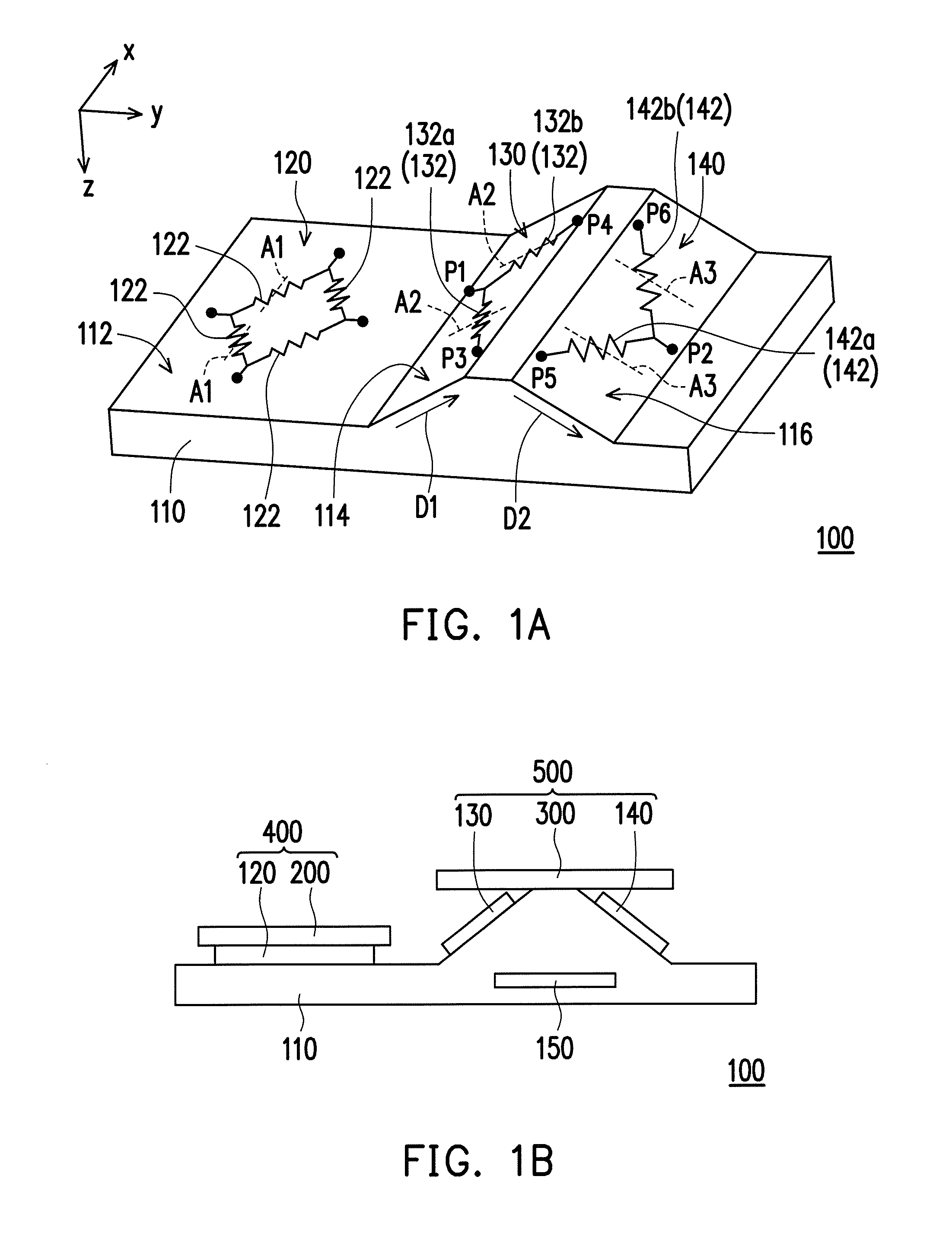
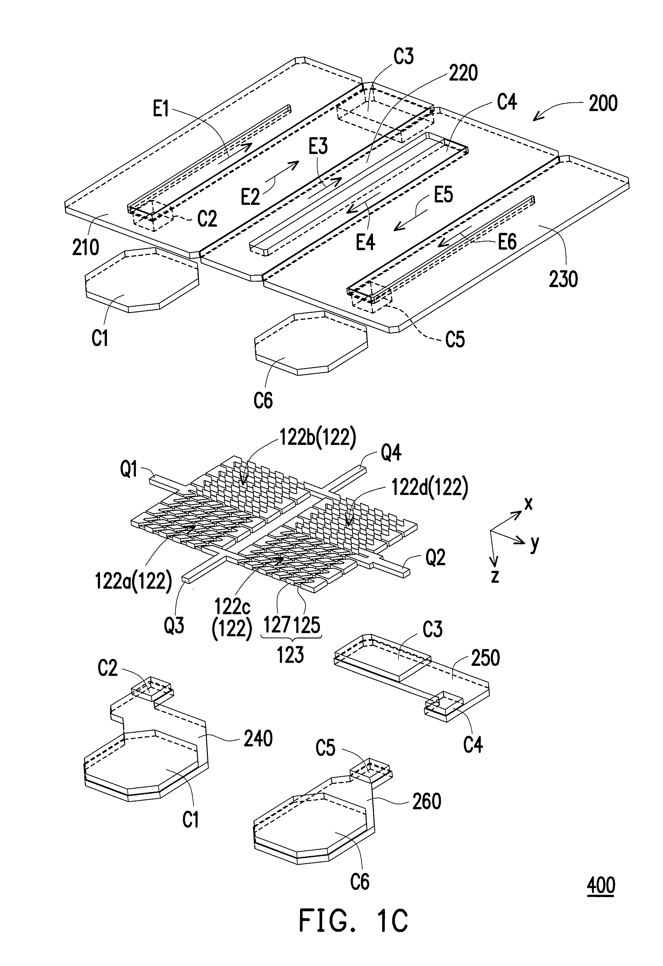
[0034]FIG. 1A is a schematic perspective view illustrating a magnetic field sensing apparatus according to an embodiment of the invention, FIG. 1B is a schematic cross-sectional view illustrating the magnetic field sensing apparatus of FIG. 1A, and FIG. 1C is an exploded view illustrating the magnetic field sensing apparatus of FIG. 1A. For the ease of illustration, FIG. 1A omits a magnetization direction setting element of FIG. 1B. Referring to FIGS. 1A to 1C, a magnetic field sensing apparatus 100 of this embodiment includes a substrate 110, a first magnetic field sensing unit 120, a second magnetic field sensing unit 130, a third magnetic field sensing unit 140, and a switching circuit 150, as sho...


PUM


Abstract

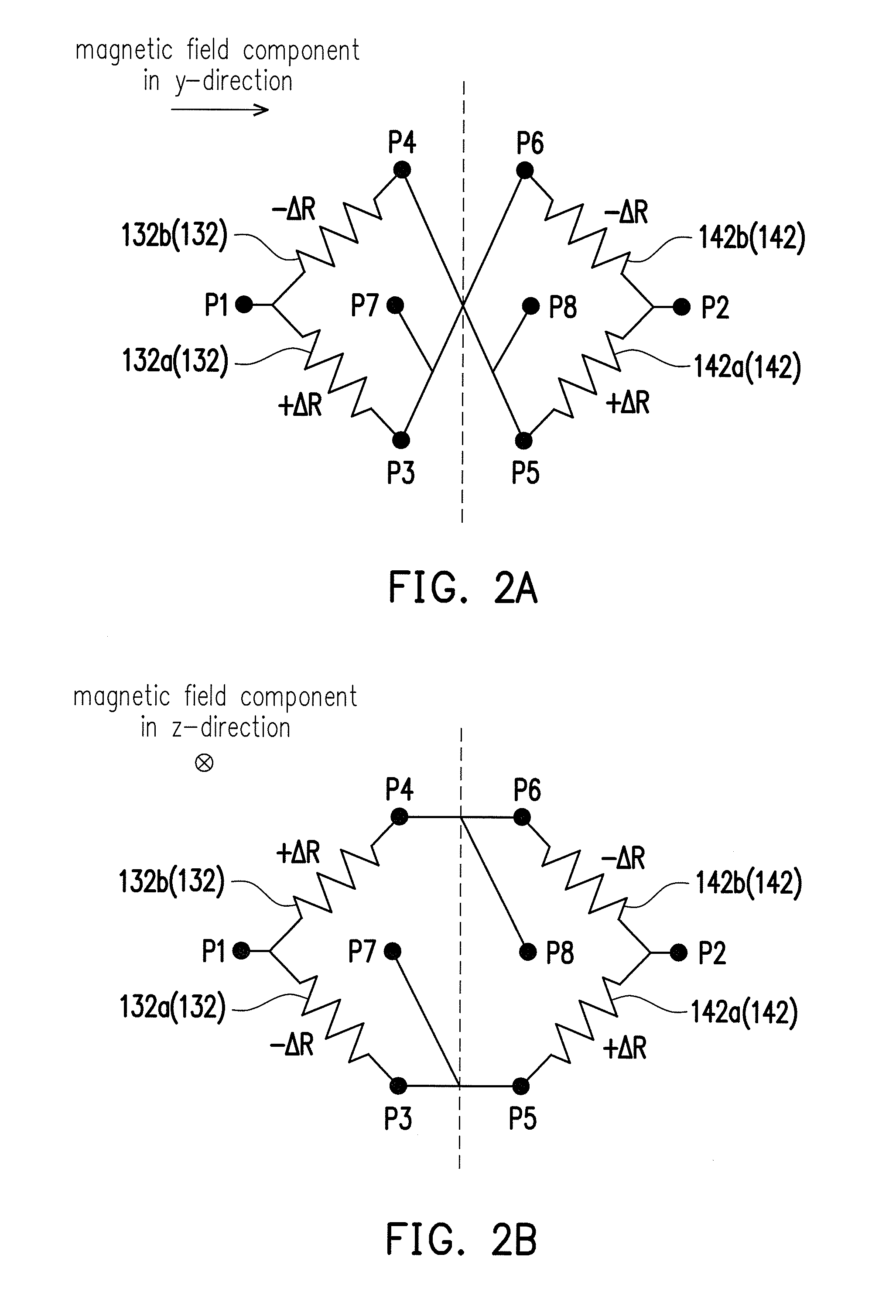
A magnetic field sensing apparatus including a substrate, first, second, and third magnetic field sensing units, and a switching circuit is provided. The substrate has a surface, and has a first inclined surface and a second inclined surface. The first magnetic field sensing unit includes a plurality of magnetoresistance sensors connected together to form a Wheatstone full bridge and disposed on the surface. The second magnetic field sensing unit includes a plurality of magnetoresistance sensors connected together to form a Wheatstone half bridge and disposed on the first inclined surface. The third magnetic field sensing unit includes a plurality of magnetoresistance sensors connected together to form a Wheatstone half bridge and disposed on the second inclined surface. The switching circuit electrically connects the second magnetic field sensing unit and the third magnetic field sensing unit. A magnetic field sensing module is also provided.

Description

CROSS-REFERENCE TO RELATED APPLICATION[0001]This application claims the priority benefits of U.S. provisional application Ser. No. 62 / 158,553, filed on May 8, 2015, and Taiwan application serial no. 105107616, filed on Mar. 11, 2016. The entirety of each of the above-mentioned patent applications is hereby incorporated by reference herein and made a part of this specification.BACKGROUND OF THE INVENTION[0002]1. Field of the Invention[0003]The invention relates to a magnetic field sensing apparatus and a magnetic field sensing module.[0004]2. Description of Related Art[0005]As portable electronic apparatuses become more and more popular, the technology of electronic compass capable of sensing the geomagnetic direction becomes highly valued. When the electronic compass is used in a small-sized portable electronic apparatus (e.g., smart phone), it is desired that the electronic compass permits tri-axial sensing in addition to meeting the requirement on size, because the user may hold t...

Claims


Application Information

Patent Timeline
Patent Type & Authority Applications(United States)
IPC IPC(8): G01R33/09G01C17/28G01R33/02
CPCG01R33/096G01C17/28G01R33/091G01R33/0206G01R33/09G01R33/093G01R33/098
Inventor YUAN, FU-TEKAO, PEI-CHUNLAI, MENG-HUANG
Owner ISENTEK INC
Learn More