
Depth map super-resolution processing method

a processing method and map technology, applied in image enhancement, image analysis, instruments, etc., can solve the problems of high cost, slow acquisition speed, and difficulty in meeting real-time requirements

Active Publication Date: 2016-11-10
SHENZHEN GRADUATE SCHOOL TSINGHUA UNIV
View PDF0 Cites 24 Cited by
  • Summary
  • Abstract
  • Description
  • Claims
  • Application Information

AI Technical Summary

Benefits of technology

The present invention is a method to process depth maps to create high-resolution images. This method uses multiple existing methods to process each block of the depth map, combining them to create a new, higher resolution image. The method matches the new image with the original image to find the highest resolution image. This results in a more accurate and useful image for practical use.

Problems solved by technology

In the existing methods of acquiring a depth map, the depth map is acquired with a laser depth scanning method, the method can acquire a high-quality high resolution depth map, but the acquisition method has higher requirements for the equipment and technology, resulting in that the cost is high, and only one point is scanned once, the acquisition speed is slow, and it is difficult to meet a real-time requirement.
Also, a scene is directly shot and acquired through a depth camera, for example, a time-of-flight (TOF) camera or the like, to rapidly obtain a depth image in real time; however, the method can only obtain a low resolution depth map, and further processing is required for obtaining a high resolution depth map.
In the existing processing methods, super-resolution processing is directly performed on the depth map with a super-resolution method, but the quality of the high resolution depth map in actual scene rendering cannot be obtained after processing, which is of little practical importance.

Method used


Image

  • Depth map super-resolution processing method
  • Depth map super-resolution processing method
  • Depth map super-resolution processing method

Examples


Embodiment Construction

[0013]The present invention is described in further detail below with reference to embodiments and the accompanying drawings.

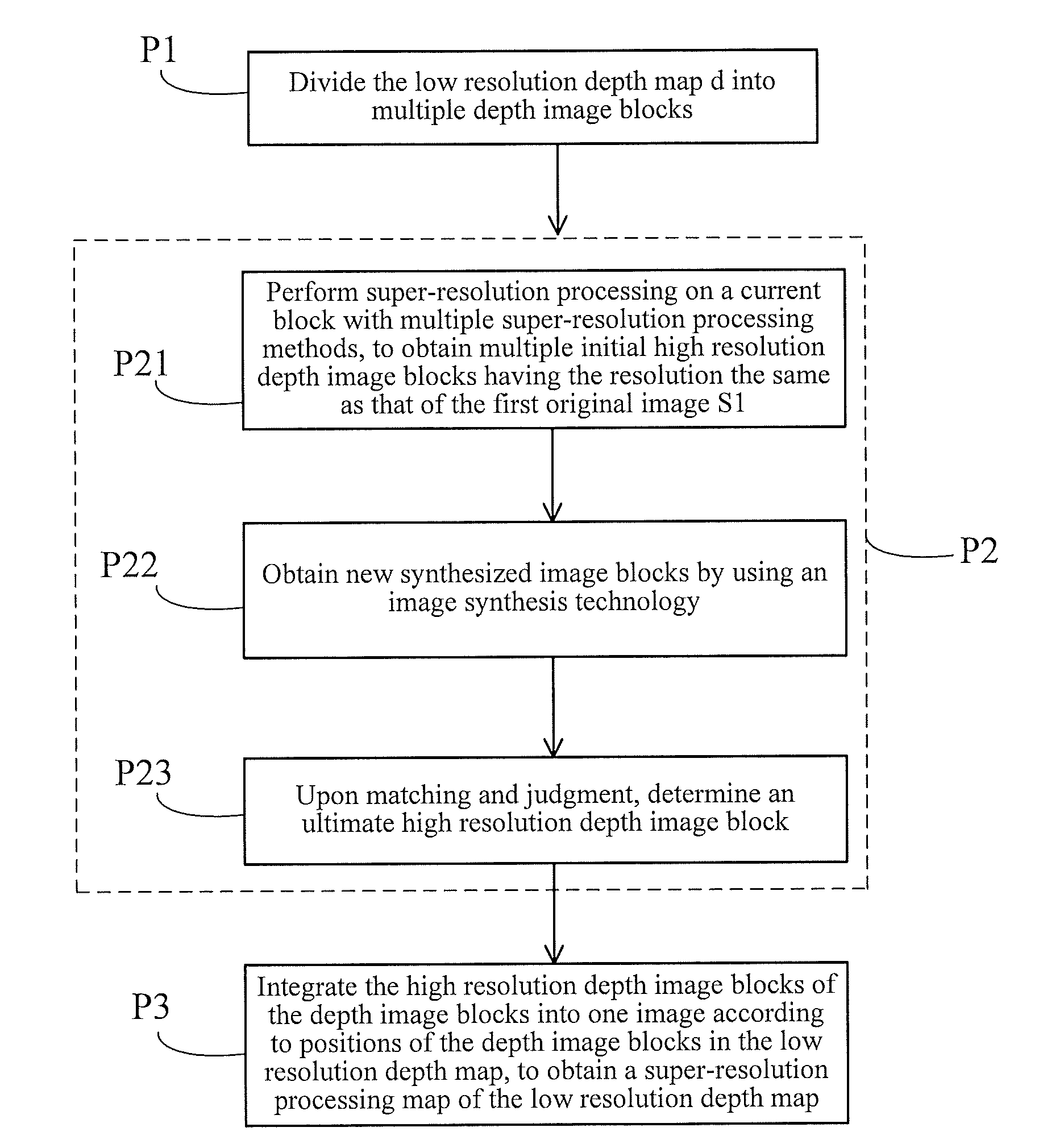
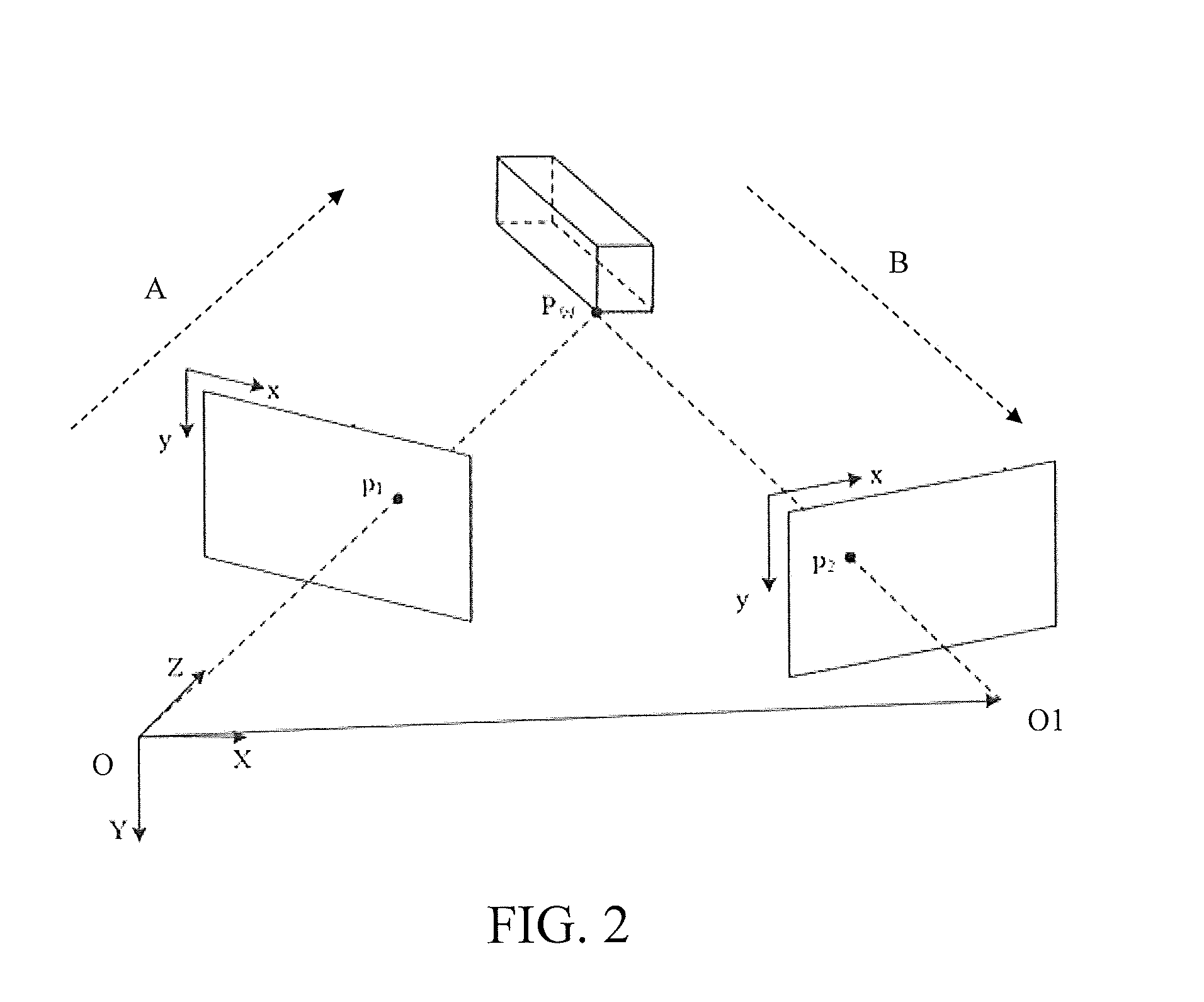
[0014]The present invention is conceived as follows: by study on a super-resolution technology and a Depth-Image-Based-Rendering (DIBR) technology, the quality of a high resolution depth map restored by the super-resolution technology is reversely verified by using a matching result of a synthesized image blocks and an original image block. In the specific embodiment, block processing is first performed on an image, a depth image block is restored to a resolution level the same as that the corresponding color image through multiple existing super-resolution technologies and then is projected to a three-dimensional space by using the restored depth image block and the corresponding image block information, then new synthesized image blocks are obtained through a virtual camera and a three-dimensional scene, the synthesized image blocks are matched with a collec...


PUM


Abstract

The present invention discloses a depth map super-resolution processing method, including: firstly, respectively acquiring a first original image (S1) and a second original image (S2) and a low resolution depth map (d) of the first original image (S1); secondly, 1) dividing the low resolution depth map (d) into multiple depth image blocks; 2) respectively performing the following processing on the depth image blocks obtained in step 1); 21) performing super-resolution processing on a current block with multiple super-resolution processing methods, to obtain multiple high resolution depth image blocks; 22) obtaining new synthesized image blocks by using an image synthesis technology; 23) upon matching and judgment, determining an ultimate high resolution depth image block; and 3) integrating the high resolution depth image blocks of the depth image blocks into one image according to positions of the depth image blocks in the low resolution depth map (d). Through the depth map super-resolution processing method of the present invention, depth information of the obtained high resolution depth maps is more accurate.

Description

BACKGROUND OF THE INVENTION[0001]1. Field of the Invention[0002]The present invention relates to the field of computer image processing, and in particular, to a depth map super-resolution processing method based on image matching[0003]2. Related Arts[0004]A super-resolution processing technology is one of the research hotspots in current disciplinary fields such as computer vision and image video processing, for processing natural images with low resolution and less detailed information and generating a high resolution image containing more detailed information, which is a technology that improves the original image resolution. The super-resolution processing technology has been widely used in fields such as high definition movie and television, image compression, medical imaging, video surveillance and satellite image analysis. Especially in recent 30 years, the super-resolution technology has been widely and deeply studied. A depth map contains three-dimensional depth information ...

Claims


Application Information

Patent Timeline
Patent Type & Authority Applications(United States)
IPC IPC(8): G06T3/40G06T7/00H04N13/00H04N13/02G06T11/60H04N13/239
CPCG06T3/4053H04N13/0203G06T11/60H04N13/0022H04N2013/0081G06T7/004G06T2207/10028G06T2207/20021G06T2207/20212G06T7/0075H04N13/111H04N13/139H04N13/239H04N13/128H04N13/204
Inventor ZHANG, LEILI, YANGGUANGZHANG, YONGBINGJIN, XINWANG, HAOQIAN
Owner SHENZHEN GRADUATE SCHOOL TSINGHUA UNIV
Learn More