Simulation modeling method for wind farm dynamic reactive power compensation capacity optimization

A simulation modeling, wind farm technology, applied in the direction of reactive power compensation, reactive power adjustment/elimination/compensation, circuit devices, etc., can solve the problem that it is difficult to fully display the reactive power and voltage variation rules of wind farms, and achieve a matching degree high effect

Inactive Publication Date: 2017-01-04
SIEYUAN QINGNENG ELECTRICAL & ELECTRONICS +2
View PDF6 Cites 0 Cited by
  • Summary
  • Abstract
  • Description
  • Claims
  • Application Information

AI Technical Summary

Problems solved by technology

[0003] At present, the traditional wind farm system modeling method is to carry out the power flow calculation and combined modeling of various reactive loads such as fans, box-type transformers, cables, and main transformers in the wind farm under specific steady-state conditions. The way of power load model parameters can simulate and reflect the reactive power and voltage changes of wind farms to a certain extent, but there is still a big difference between this method and the steady state and transient changes of actual reactive power and voltage on site, and it is difficult to fully display the wind power. Variation law of field reactive power and voltage

Method used


Image

  • Simulation modeling method for wind farm dynamic reactive power compensation capacity optimization

Examples


Embodiment Construction

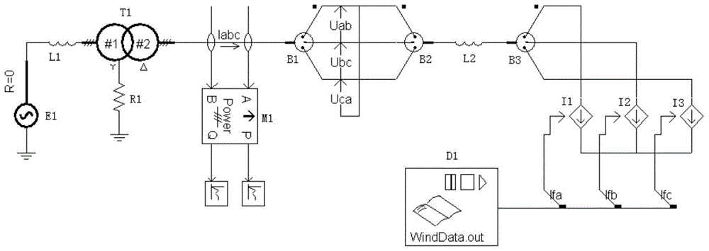
[0022] The technical solutions of the present invention will be further described below in conjunction with the accompanying drawings and embodiments.

[0023] Such as figure 1 The wind farm system model is shown based on the actual wave recording data in the field. In the model, E1 is the system power supply, L1 and L2 are the equivalent inductance of the simulated line, T1 is the main transformer of the wind farm, and M1 is the active and reactive power of the low-voltage side of the main transformer. Power measurement module, Iabc, Uab, Ubc, Uca are main transformer low-voltage side phase current and line voltage measurement modules respectively, B1~B3 are line splitters, I1, I2, I3 are wind farm system equivalent load reactive current sources , D1 is the reactive current data file imported into the PSCAD simulation environment after the actual measured data of the wind farm is converted, and the three-phase reactive current Ifa, Ifb, Ifc is output to control the load curre...


PUM


Abstract

The invention discloses a simulation modeling method for optimizing a dynamic reactive power compensation capacity of a wind farm. The simulation modeling method comprises the following steps: firstly, establishing a wind farm system model, wherein the wind farm system model adopts PSCAD software; then, respectively arranging measuring points at the high and low voltage sides of a field main transformer, each electricity gathering wire and a selected fan of the wind farm, recording electric variable data of the field measuring points of the wind farm in real time by utilizing a power quality monitoring instrument, converting the electric variable data into reactive current data, importing the reactive current data into a File Read module of a PSCAD simulation environment, and outputting the reactive current data to respectively control load equivalent reactive current sources of the wind farm, wherein the electric variable data includes current, voltage, active power, reactive power and a power factor of each measuring point; and then, by amending line equivalent inductance parameters at the two sides of the main transformer in the wind farm system model, enabling the voltages at the two sides of the main transformer in the wind farm system model to be consistent to actual field wave recording data of the wind farm so as to achieve the purpose of truly simulating filed reactive power and voltage transformation of the wind farm.

Description

technical field [0001] The invention relates to the neighborhood of wind power generation, and more specifically relates to a simulation modeling method for dynamic reactive power compensation capacity optimization of wind farms. Background technique [0002] During the use of wind power generation, due to the influence of wind speed and other environmental factors, the intermittence of wind power generation is more obvious, and the active power, reactive power and voltage of the access point of the wind farm will continue to change. At present, most wind farms use in-situ dynamic reactive power Compensation method to solve the impact of power quality deterioration caused by wind farm reactive power fluctuations. In order to evaluate the dynamic reactive power compensation capacity of the wind farm based on the actual operation of the wind farm, it is necessary to model the wind farm system, and then optimize the design based on the steady-state and transient simulation resu...

Claims


Application Information

Patent Timeline
Patent Type & Authority Patents(China)
IPC IPC(8): H02J3/18
CPCH02J3/18H02J2203/20Y02E40/30
Inventor 孙大南李岩赵香花陈远华王天宇
Owner SIEYUAN QINGNENG ELECTRICAL & ELECTRONICS
Why Eureka
Try Eureka