Solar panel racking array

a solar panel and array technology, applied in the direction of solar heat collector mounting/support, photovoltaics, solar heat collector safety, etc., can solve the problems of time-consuming assembly and complex system, and achieve the effect of maximising the effect of improving the effect of wind load

Inactive Publication Date: 2016-11-10
POWERAK
View PDF4 Cites 5 Cited by
  • Summary
  • Abstract
  • Description
  • Claims
  • Application Information

AI Technical Summary

Benefits of technology

[0028]A truncated T-rack was designed preferably to (if needed) support a perimeter fence panel. The fence panel incorporates adaptations for either the T-rack or the truncated T-rack to fix singly or on both sides on one [the first], end of the fence panel if more support is required. Extruded tongues were moulded on the other end of the fence panel, to provide connectivity and thermal expansive release via slots cut into the first end of the next connected panel. The fence panel is designed to be 60% porous with sinusoidal form factor to maximise its ameliorating effectiveness on wind loads. The fence panel is incorporated with tongue and groove adaptations together with fixing boltholes so that it can be assembled in a corral formation. Preferably the fence panel has a blunt front mesh type air-foil profile with a specific wind porosity requirement. The air foil profile is preferably curved back over the rack array.

Problems solved by technology

This system appears complex and time consuming to assemble.

Method used


Image

  • Solar panel racking array
  • Solar panel racking array
  • Solar panel racking array

Examples


Embodiment Construction

[0044]A preferred embodiment of the invention will be described with reference to the drawings in which:

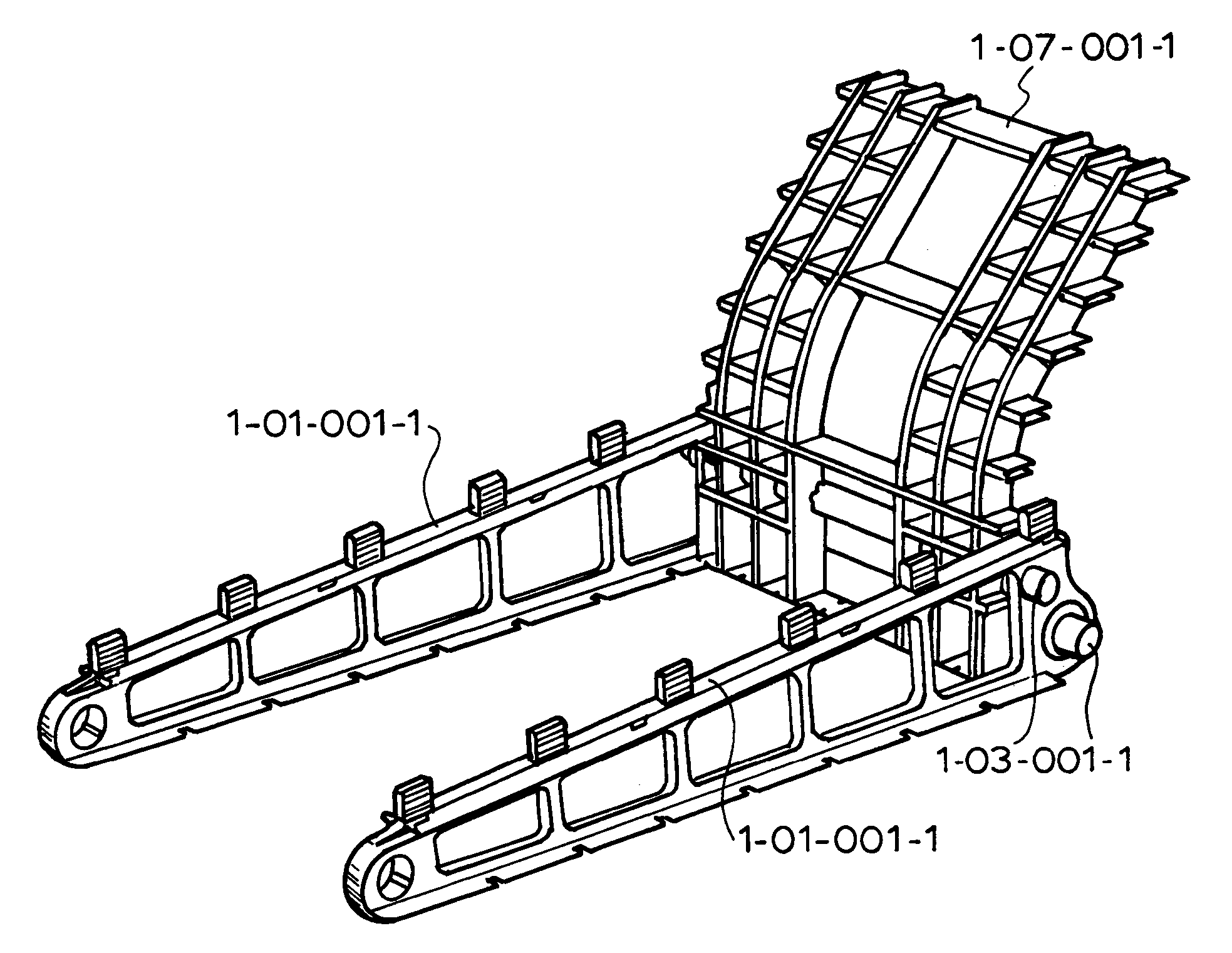
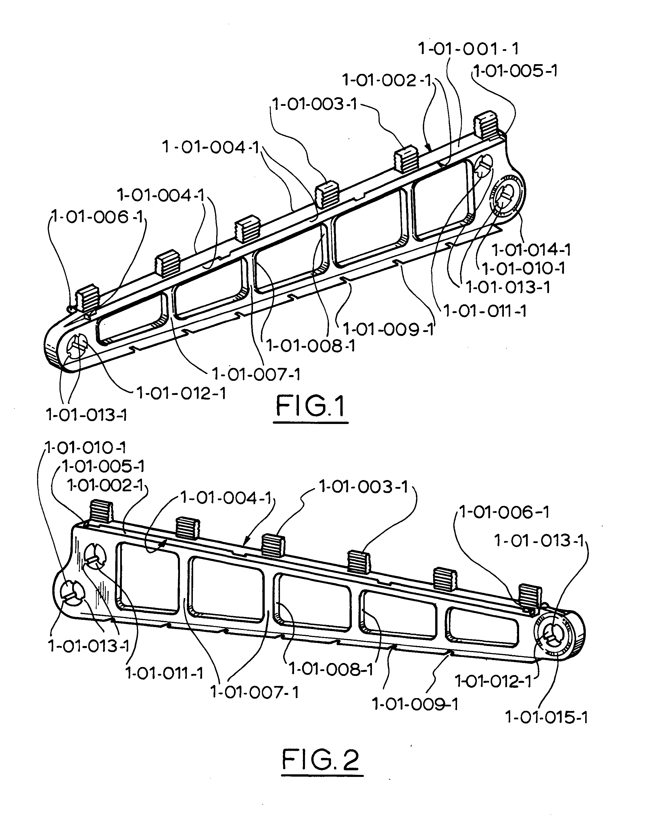
[0045]FIG. 1 illustrates a RHS isometric view of the Truss Rack;

[0046]FIG. 2 illustrates a LHS isometric view of the Truss Rack;

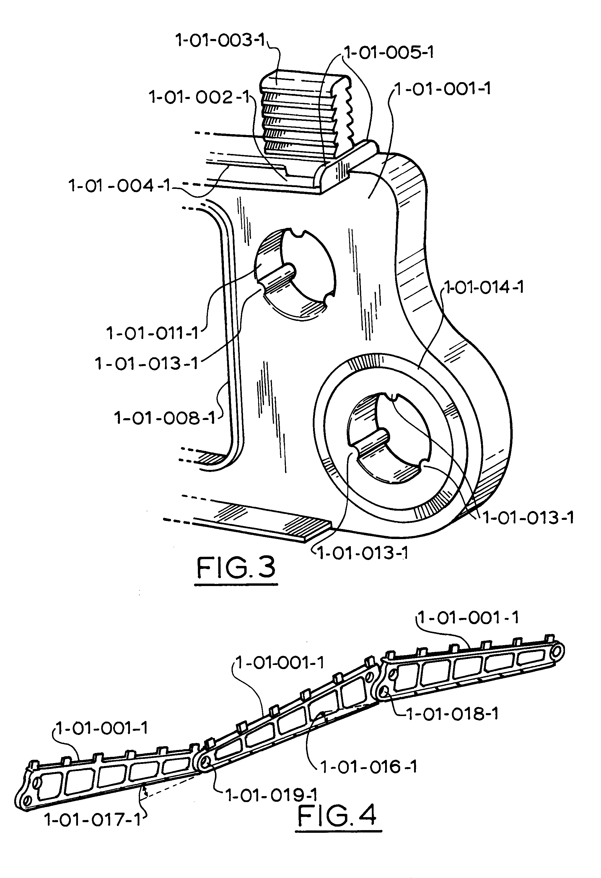
[0047]FIG. 3 illustrates a magnified view of the larger end of FIG. 1;

[0048]FIG. 4 illustrates three truss racks assembles front-to-front and back-to-back;

[0049]FIG. 5 illustrates the two embodiments of the solar panel restraining clip;

[0050]FIG. 6 illustrates the clip [first embodiment] assembled on an array fixing a PV panel;

[0051]FIG. 7 illustrates an assembly of: Four REC Solar [1667×993 mm], panels mounted on six T-racks, fixed with retaining clips, in portrait orientation;

[0052]FIG. 8 illustrates an assembly of: Four REC Solar [1667×993 mm], panels mounted on four T-racks, fixed with retaining clips, in landscape orientation;

[0053]FIG. 9 illustrates an assembly of: Three First Solar [1200×600 mm], amorphous panels mounted on two T-racks, fixed with ...


PUM


Abstract

A commercial modular solar racking system, with the capability to be assembled in several configurations, which when assembled, creates a adaptable, size variable, solar panel supporting infrastructure, with a rapid assembly time. The said modular system can be adapted, to construct a perimeter wind lift-dampening fence around the deployed array. This modular rack array for supporting solar panels includes solar panel hold down clips; a longitudinal support rack which is securable to a roof and which has two longitudinal sides with solar panel support ledges on both sides and hold down clip receiving recesses located between each row of support ledges the arrangement enabling a single solar panel to be supported by two parallel support racks and additional panels to be supported by an additional support rack with the panel hold down clips being arranged to be secured to the support racks by clipping into the receiving recesses in said support racks and bearing down on the upper side of the solar panel edges so that two parallel edges of said solar panel are held between the hold down clips and the support ledges of said support racks. The invention also provides a residential modular racking system for pitched roofs, with the capability to incrementally adjust to suit any large PV panel size. The system is based on four, quarter size racks sliding into each other providing the variability. Each support module for supporting solar panels on pitched roofs has connection projections on two adjoining sides and on the two opposed adjoining sides are complementary connection recesses so that the modules are interconnectable.

Description

[0001]This invention relates to a modular solar racking system. This invention addresses the problems of installation time and wind stability of installed arrays particularly on roof tops.BACKGROUND TO THE INVENTION[0002]Patent WO2000012839 discloses a solar panel roof mounting system. This system appears complex and time consuming to assemble. This system relies on under tile fixing and the inherent system weight. There is no lower fixing mechanism to address fixing from the facia side of the roof, and further: The strapping mechanism has no inherent North-South & East-West, cross-fixing mechanism. The fixing system is a non-tensioned system. The straps are illustrated fixed to the top tile battens, The system without the necessary cross tensioning, and strong, stable fixing points, will not endure medium-to-high wind speeds, and would predictably oscillate / vibrate / lift when affected by variable wind gusts.[0003]For some time there has been interest in the use of thermoplastics for...

Claims


Application Information

Patent Timeline
Patent Type & Authority Applications(United States)
IPC IPC(8): H02S20/23H02S30/10H02S20/30
CPCH02S20/23H02S30/10H02S20/30H02S20/00Y02E10/50Y02B10/20Y02E10/47F24S40/85F24S25/61F24S2025/6008F24S80/30F24S25/16F24S25/11F24S25/50F24S25/634Y02B10/10
Inventor CAP, GEORGE JAROSLAVFRIES, WILLIAM M.
Owner POWERAK
Why Eureka
Try Eureka