Sheet manufacturing apparatus

a technology of sheet manufacturing and manufacturing apparatus, which is applied in the direction of manufacturing tools, applications, other domestic articles, etc., can solve the problems of large equipment, time-consuming maintenance of water treatment facilities, and significant energy required in the drying process

Active Publication Date: 2016-11-17
SEIKO EPSON CORP
View PDF4 Cites 28 Cited by
  • Summary
  • Abstract
  • Description
  • Claims
  • Application Information

AI Technical Summary

Benefits of technology

[0013]In the sheet manufacturing apparatus of the invention, the deposition unit has a conveyor unit that moves while the precipitate is deposited thereon, and the control unit variably controls the speed of the conveyor unit.
[0018]Because the sheet manufacturing apparatus can change the size of the screen openings of the sieve unit, the fiber length of the defibrated material passing the sieve unit can be changed, and the strength and density of the manufactured sheets can be changed in a single production apparatus.

Problems solved by technology

Such wet process sheet manufacturing apparatuses require a large amount of water and large-scale equipment.
Maintenance of a water treatment facility is also time-consuming, and significant energy is required for a drying process.

Method used


Image

  • Sheet manufacturing apparatus
  • Sheet manufacturing apparatus
  • Sheet manufacturing apparatus

Examples


example 1

2.1. Example 1

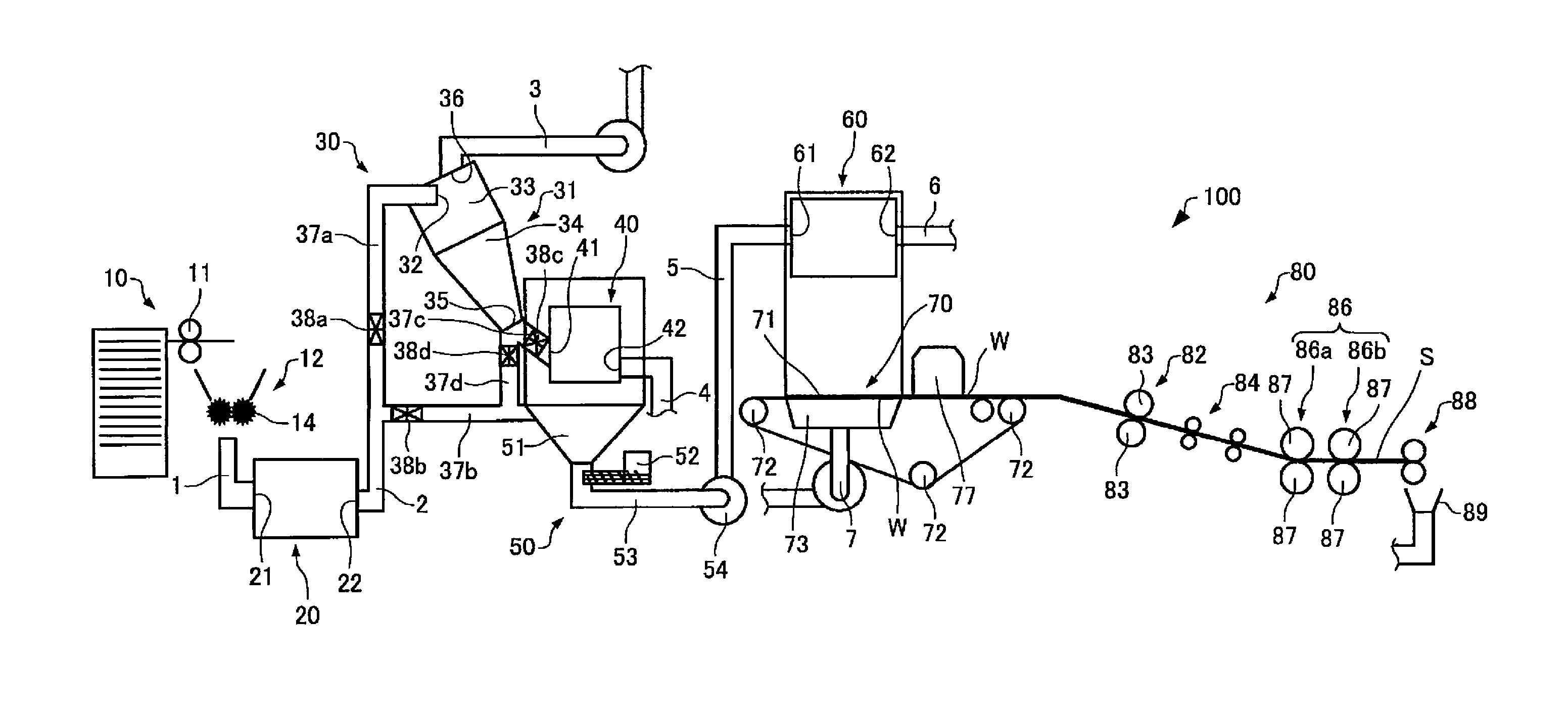
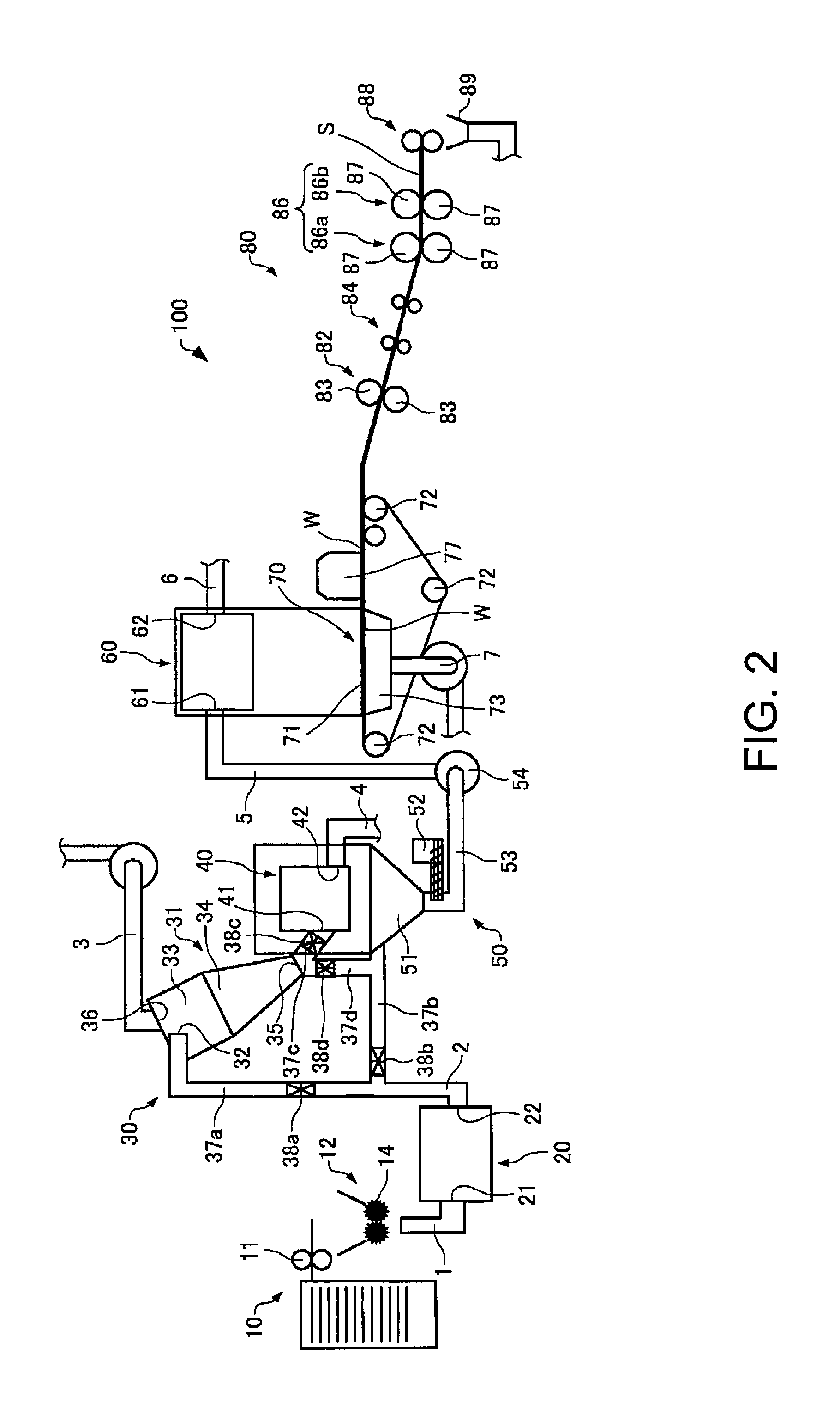
[0100]In example 1, recovered printed paper (recovered paper that has already been printed on) was supplied as the feedstock from the supply unit 10 as shown in FIG. 3. A paper shredder was used as the shredder 12, and the feedstock (recovered paper that has been printed on) supplied from the supply unit 10 was cut into shreds approximately 6 mm×14 mm.

[0101]A defibrator was used as the defibrating unit 20, which defibrated the feedstock after being shredded in the shredder 12. The speed of the defibrating unit 20 (rotational speed of the rotating part of the defibrating unit 20) was 5000 rpm.

[0102]A cyclone was used as the classifying unit 31 of the classifier 30, and classified defibrated material that past the defibrating unit 20.

[0103]A cylindrical sieve (rotary sifter) that can rotate was used as the separator 40, which sifted the classified material from the classifier 30 by fiber length. Mesh with 970 μm screen openings was used as the screen of the separator 40....

example 2

2.2. Example 2

[0109]Of the plural additive supply units 52 in example 2, the second additive supply unit, which supplied 15 parts by weight of colored resin particles, was selected and resin was supplied from the second additive supply unit. This example was otherwise identical to example 1.

[0110]Blue paper is made in example 2.

[0111]As will be understood by comparing example 1 and example 2, a sheet manufacturing apparatus 100 having multiple additive supply units 52 can make different colors of paper by selecting the additive supply unit 52 that supplies the additive. Note that the sheet manufacturing apparatus 100 may be configured with only one additive supply unit 52, and the type of additive that is supplied may be changed by replacing the cartridge (a cartridge loaded with additive) of the additive supply unit 52, for example.

example 3

2.3. Example 3

[0112]Pulp sheet was supplied as the feedstock from the supply unit 10 in example 3. Defibrated material defibrated in the defibrating unit 20 was conveyed to the mixing unit 50 without passing the classifying unit 31 and separator 40 in example 3. More specifically, the first valve 38a was closed, the second valve 38b was open, and the defibrated material was conveyed to the mixing unit 50. In addition, 100 parts by weight defibrated material (fiber), 15 parts by weight polymer fiber, and 5 parts by weight flame retardant were mixed in example 3. Of the multiple additive supply units 52, the third additive supply unit that supplies polymer fiber, and the fourth additive supply unit that supplies a flame retardant, were selected to supply. In example 3, mesh with a 3000 μm screen opening was used as the screen of the sieve unit 60. Of the multiple forming units 80 in example 3, a forming unit 80 having three sets of heat rollers 87 and no calendar rolls 83 was selected...


PUM

PropertyMeasurementUnit
lengthaaaaaaaaaa
lengthaaaaaaaaaa
diameteraaaaaaaaaa

Abstract

A sheet manufacturing apparatus can process various materials and manufacture a variety of sheets by changing conditions for making the sheets. A sheet manufacturing apparatus according to the invention has a supply unit that supplies feedstock; a defibrating unit that defibrates the feedstock; a classifier that classifies defibrated material that past the defibrating unit; a mixing unit that mixes an additive containing resin with the classified material that past the classifier; a sieve unit that passes the mixture that past the mixing unit through many openings; a deposition unit that deposits precipitate that past many openings in the sieve unit; a forming unit that applies pressure and heat to the web deposited on the deposition unit, forming a sheet; and a control unit that changes a condition of at least one of the classifier, mixing unit, sieve unit, deposition unit, and forming unit.

Description

TECHNICAL FIELD[0001]The present invention relates to a sheet manufacturing apparatus.BACKGROUND[0002]Conventional sheet manufacturing apparatuses use a wet process in which feedstock containing fiber is soaked in water and then defibrated and repulped by primarily mechanical means. Such wet process sheet manufacturing apparatuses require a large amount of water and large-scale equipment. Maintenance of a water treatment facility is also time-consuming, and significant energy is required for a drying process. Dry-process sheet manufacturing apparatuses requiring little water have therefore been proposed to reduce device size and save energy.[0003]For example, PTL 1 describes a paper recycling apparatus that defibrates shredded paper into fibers in a dry defibrator and makes paper. PTL 2 describes an apparatus for manufacturing insulation containing three-dimensional structures of nonwoven cloth containing short fibers.CITATION LISTPatent Literature[0004][PTL 1] JP-A-2012-144819[0005...

Claims


Application Information

Patent Timeline
Patent Type & Authority Applications(United States)
IPC IPC(8): B27N3/04B27N1/00D04H1/60B27N3/00D04H1/4274D21B1/06B27N1/02
CPCB27N3/04D21B1/06B27N1/00D04H1/60B27N3/002D04H1/4274B27N1/02D21F9/00Y02W30/64D01G25/00
Inventor MURAYAMA, YOSHIAKISEKI, SHUNICHIGOMI, KATSUHITO
Owner SEIKO EPSON CORP
Why Eureka
Try Eureka