Methods and systems for selectively adapting engine air flow

a selective adapter and engine technology, applied in the direction of engines, machines/engines, electric control, etc., can solve the problems of engine air-fuel ratio deviating from the desired air-fuel ratio, air-fuel ratio error, air-fuel error, etc., to improve engine air-flow estimates, reduce a number of variables, and reduce engine air-flow variability.

Active Publication Date: 2016-11-17
FORD GLOBAL TECH LLC
View PDF3 Cites 2 Cited by
  • Summary
  • Abstract
  • Description
  • Claims
  • Application Information

AI Technical Summary

Benefits of technology

[0004]By updating a first engine air flow related transfer function responsive to motor / generator conditions and a second engine air flow related transfer function, it may be possible to improve engine air flow estimates without having to rely on estimated exhaust gas concentrations. Further, by not using an oxygen sensor to estimate engine air flow it may be possible to reduce a number of variables that may influence engine air flow determination. For example, it may be possible to estimate engine air flow when an engine is rotating but not combusting air and fuel. Consequently, parameters that may influence air flow through the engine, such as fuel properties and spark timing, may be eliminated from engine air flow estimates so that engine air flow variability may be reduced.
[0005]The present description may provide several advantages. Specifically, the approach may improve vehicle efficiency over a vehicle's life cycle. Further, the approach may reduce engine air-fuel mixture variation. Further still, the approach may improve engine torque control by improving engine torque estimates.

Problems solved by technology

During some conditions, the engine's air-fuel ratio may deviate from a desired air-fuel ratio due to manufacturing variation or degradation of engine components.
One source of engine air-fuel ratio error may be fuel injectors not delivering a desired or expected amount of fuel.
Another source of engine air-fuel error may be an inaccurate engine air flow estimate based on an engine air flow sensor.
An aggregate air-fuel ratio error may be determined via an oxygen sensor position in the engine's exhaust system, but the aggregate error provides little insight into whether the air-fuel error is a result of fueling or the engine air flow estimate.
However, if the engine air-fuel error was actually a result of an engine air flow estimate, adjustments to engine air flow related actuators and determination of engine air flow related control parameters, such as engine torque, may be improper.
Further, the approach may reduce engine air-fuel mixture variation.

Method used


Image

  • Methods and systems for selectively adapting engine air flow
  • Methods and systems for selectively adapting engine air flow
  • Methods and systems for selectively adapting engine air flow

Examples


Embodiment Construction

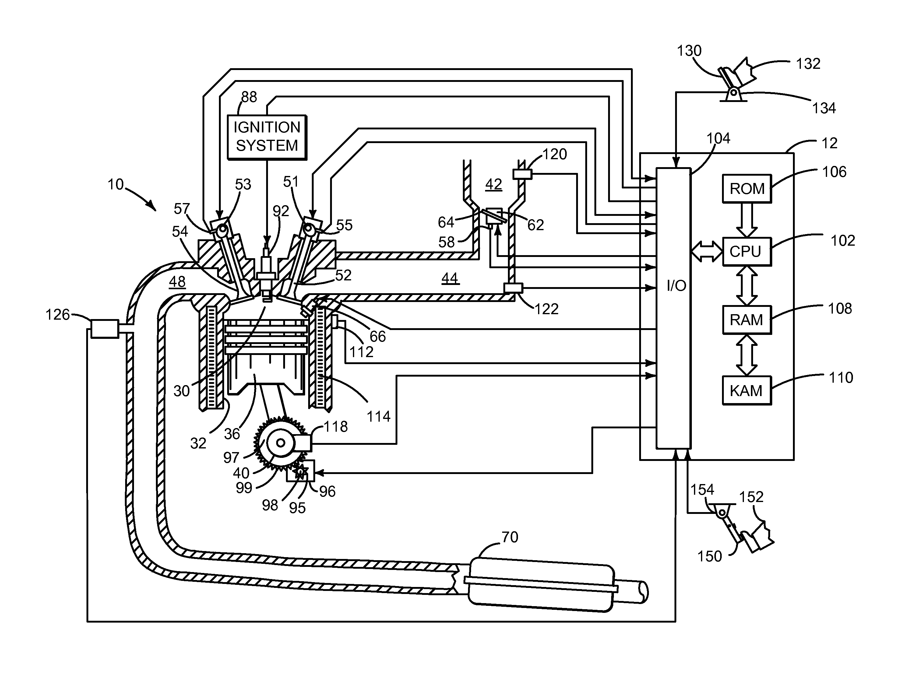
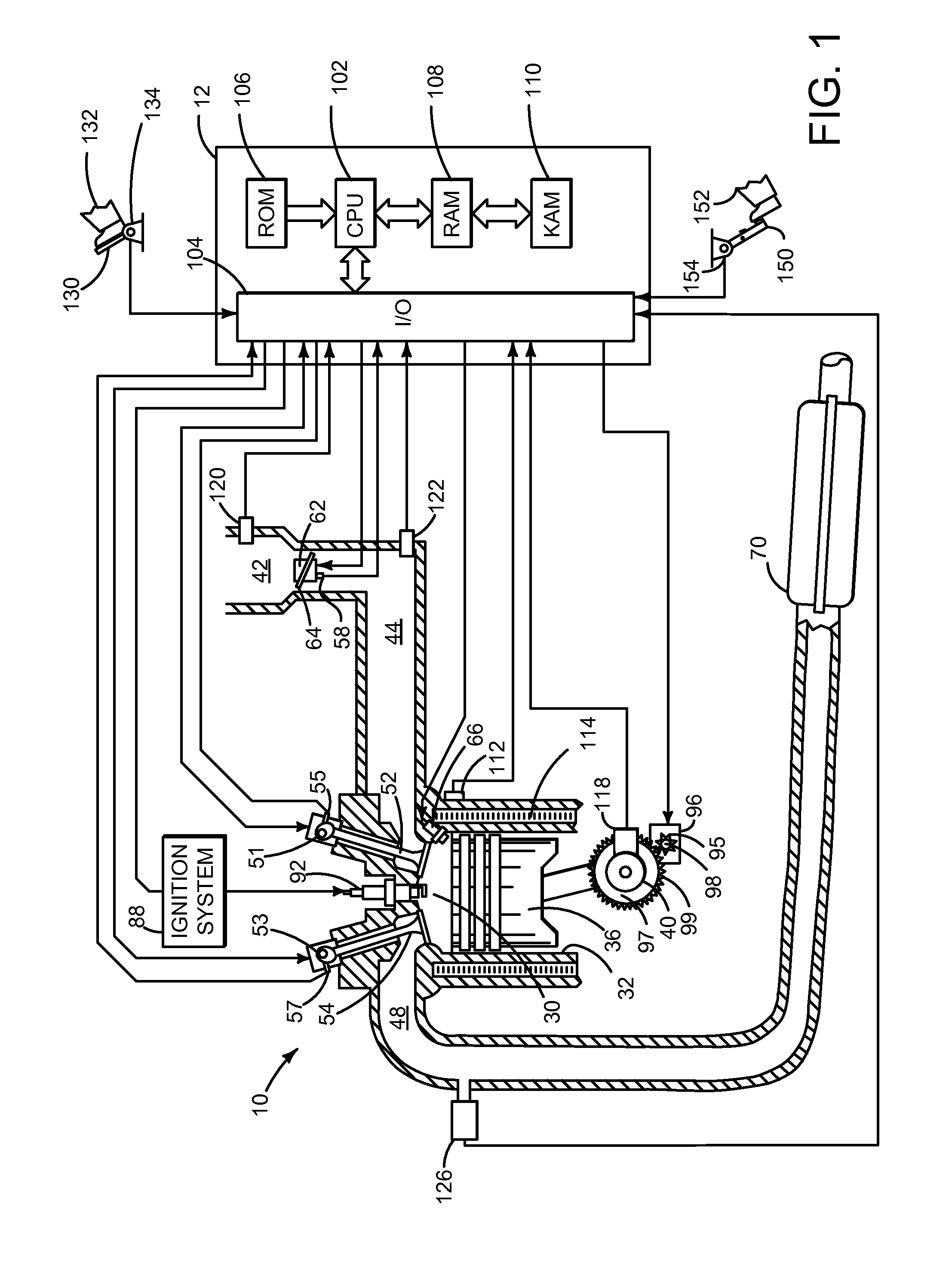
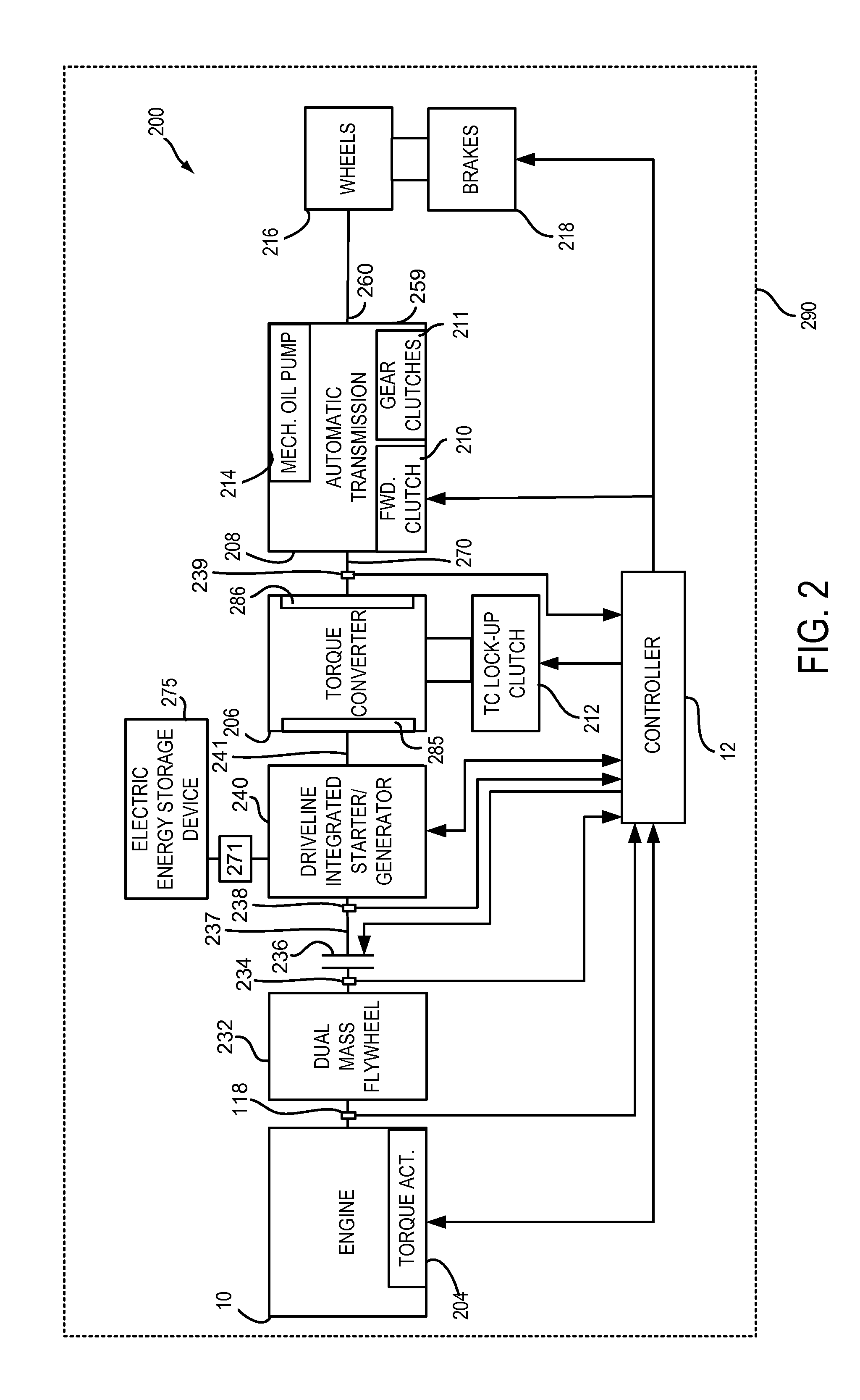
[0013]The present description is related to revising one or more transfer functions describing engine air flow and making adjustments to engine actuators based on the revised transfer functions. The transfer functions may be revised based at least on operation of a motor / generator of a hybrid vehicle driveline. The hybrid vehicle driveline may include an engine as shown in FIG. 1 that may be selectively coupled to a motor / generator to provide input to a transmission as is shown in FIG. 2. Alternatively, the engine of FIG. 1 may be included in a power split hybrid driveline with a motor and a generator as is shown in FIG. 3. A method for adjusting engine air flow and engine actuators is shown in FIGS. 4A and 4B.

[0014]Referring to FIG. 1, internal combustion engine 10, comprising a plurality of cylinders, one cylinder of which is shown in FIG. 1, is controlled by electronic engine controller 12. Engine 10 includes combustion chamber 30 and cylinder walls 32 with piston 36 positioned t...


PUM


Abstract

Systems and methods for adjusting an engine air flow transfer function and engine actuators based on the engine air flow transfer function are presented. The system and method may be applied to hybrid powertrains having a capability to estimate engine torque based on operating characteristics of a motor during vehicle operation.

Description

FIELD[0001]The present description relates to a system and method for adjusting an engine air flow transfer function and engine actuators responsive to the engine air flow transfer function. The methods and systems may be useful for a variety of hybrid drivelines including series and parallel configurations.BACKGROUND AND SUMMARY[0002]An engine's air-fuel ratio may be controlled to reduce engine emissions. During some conditions, the engine's air-fuel ratio may deviate from a desired air-fuel ratio due to manufacturing variation or degradation of engine components. One source of engine air-fuel ratio error may be fuel injectors not delivering a desired or expected amount of fuel. Another source of engine air-fuel error may be an inaccurate engine air flow estimate based on an engine air flow sensor. An aggregate air-fuel ratio error may be determined via an oxygen sensor position in the engine's exhaust system, but the aggregate error provides little insight into whether the air-fue...

Claims


Application Information

Patent Timeline
Patent Type & Authority Applications(United States)
IPC IPC(8): B60W20/15F02D41/14B60W10/06
CPCB60W20/15B60W10/06Y10S903/902B60W2510/06B60W2710/0666F02D41/1454F02D41/18F02N11/04F02D2200/0411F02D2200/1004B60K6/48B60K2006/4825B60W2050/0088B60W2710/0633B60W2510/0657B60W2510/083Y02T10/62
Inventor MILLER, KENNETH JAMESMARTIN, DOUGLAS RAYMONDANDERSON, BRUCE COLBY
Owner FORD GLOBAL TECH LLC
Why Eureka
Try Eureka