Vibrating micro-mechanical sensor of angular velocity

a micro-mechanical sensor and vibration technology, applied in the direction of speed measurement using gyroscopic effects, instruments, surveying and navigation, etc., can solve the problems of gyroscope devices, rate signal noise, rate offset instability, etc., and achieve the effect of reducing problems

Active Publication Date: 2016-11-17
MURATA MFG CO LTD
View PDF4 Cites 15 Cited by
  • Summary
  • Abstract
  • Description
  • Claims
  • Application Information

AI Technical Summary

Benefits of technology

[0009]An object of the present invention is to provide a method and apparatus so as to overcome the prior art disadvantages and specifically to alleviate problems caused by non-zero total angular momentum.

Problems solved by technology

In a gyroscope device, combination of multiple moving masses may cause total angular momentum in addition to total linear momentum, both of which may cause some problems in the gyroscope device.
For example, non-zero total momentum may cause instability of rate offset, rate signal noise, susceptibility to and / or interference with external mechanical shock and vibration in addition to problems caused during start up time, which will be described in more detail later.

Method used


Image

  • Vibrating micro-mechanical sensor of angular velocity
  • Vibrating micro-mechanical sensor of angular velocity
  • Vibrating micro-mechanical sensor of angular velocity

Examples


Embodiment Construction

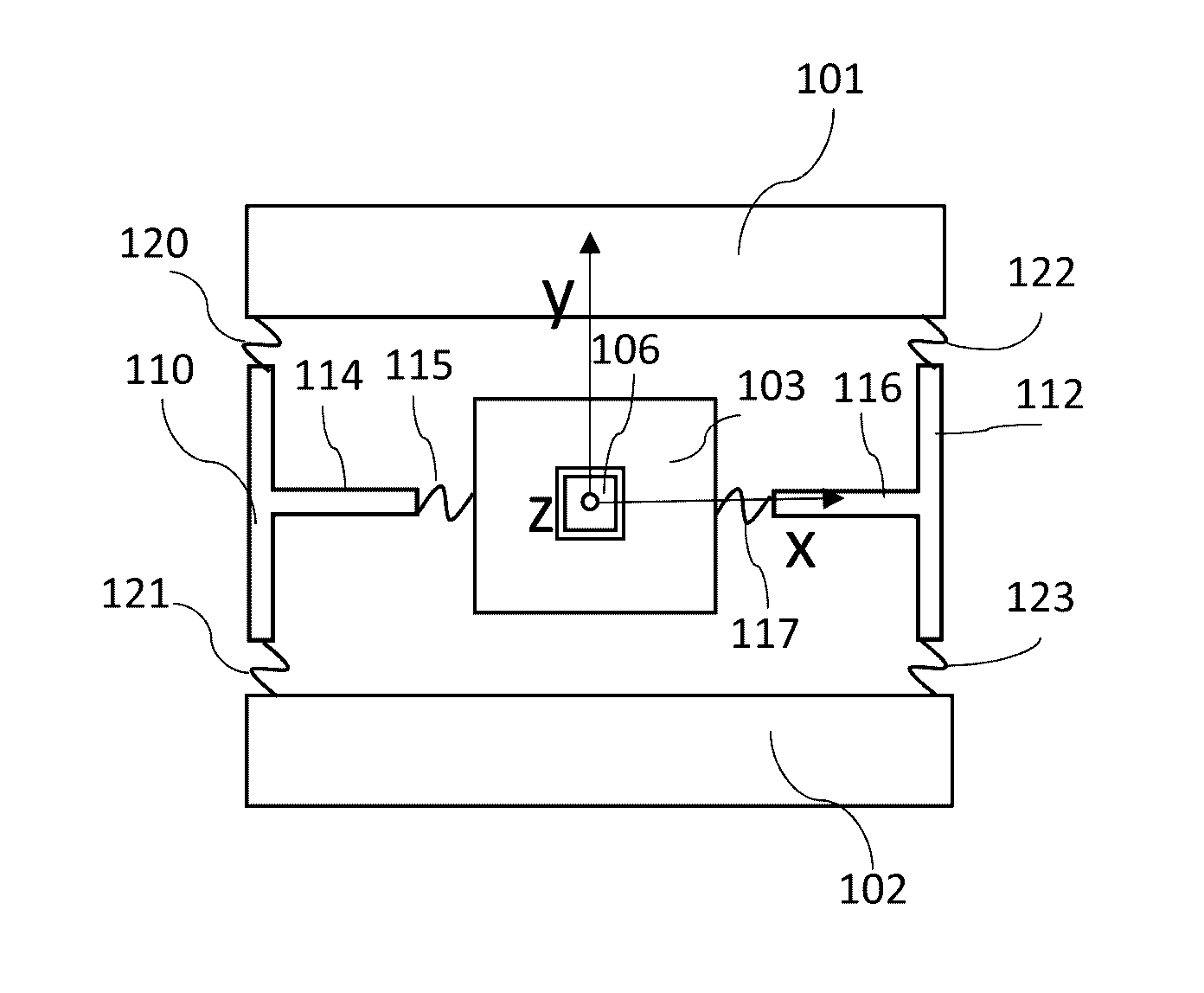
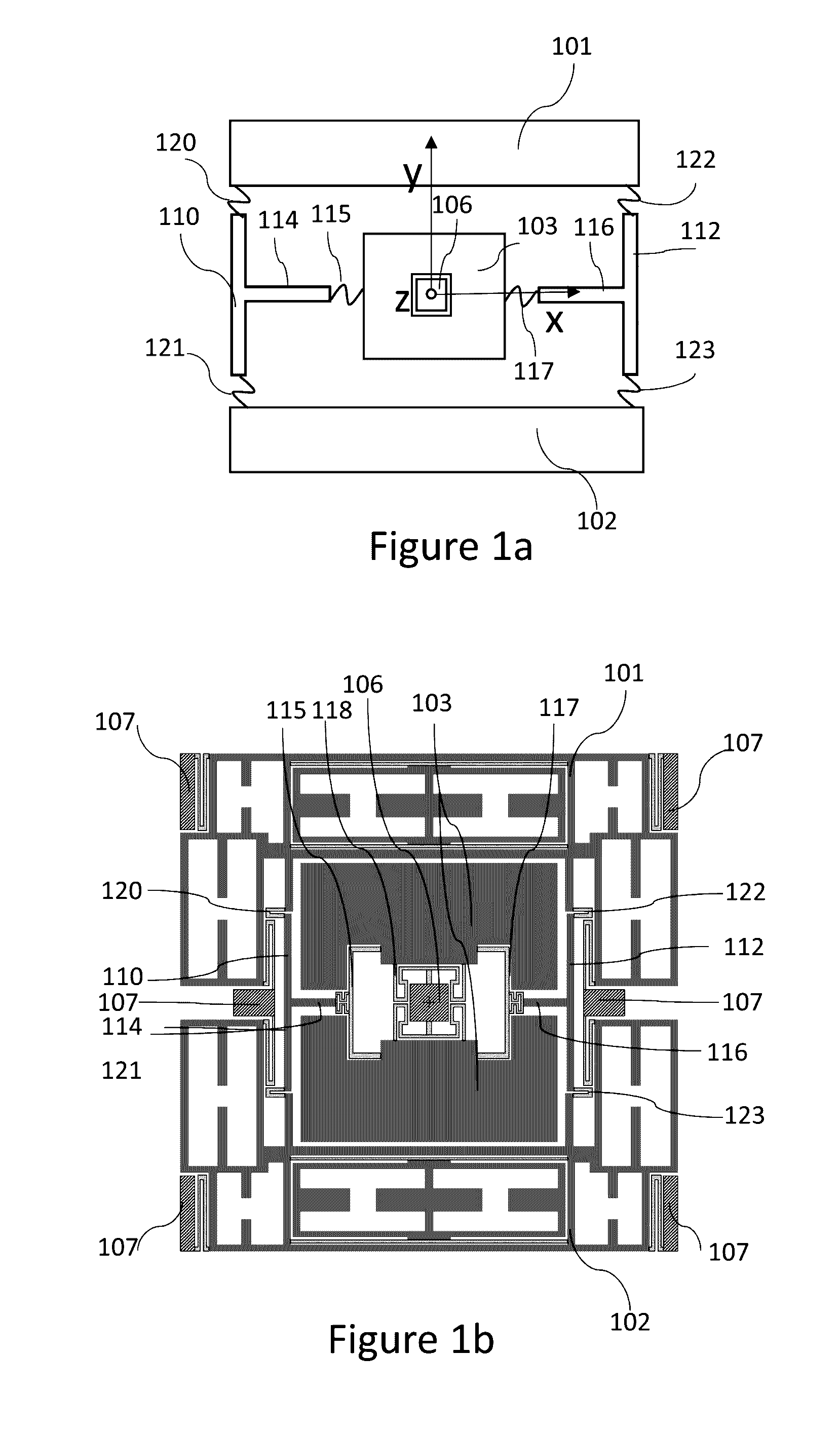
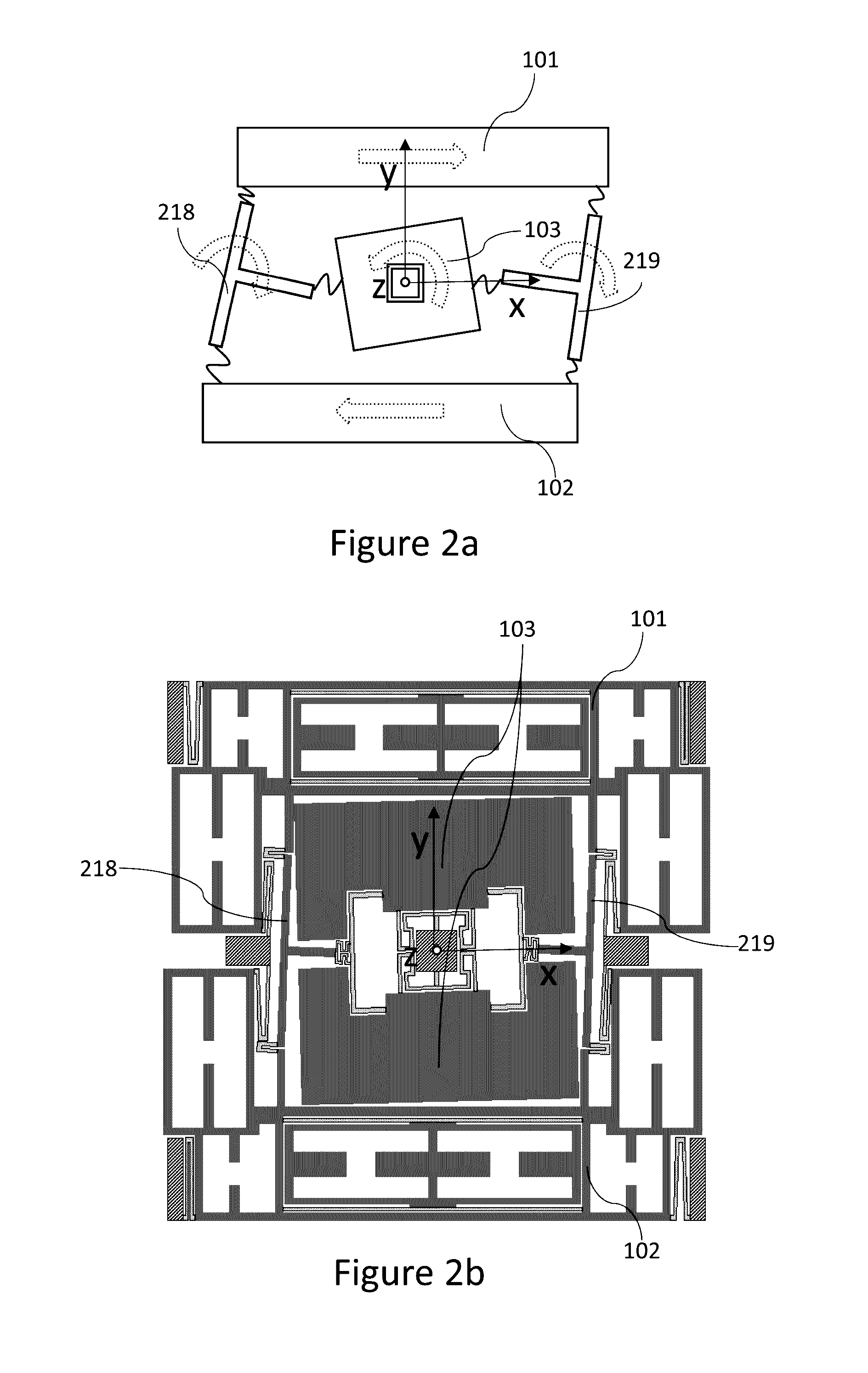
[0040]With reference to “plane of the device”, “plane of the structure”, “plane of the sensor”, “plane of the masses” or “plane of the rotor mass”, we mean a plane formed by inertial masses of the sensor device in their initial position when not excited to any movement. In the coordinates in the figures of this document, this plane corresponds to the xy-plane. Inertial masses of a physical device have a non-zero thickness in direction of the z-axis. The plane of these masses should be understood to comprise a flat plane comprised within the thickness of the respective referred structural elements.

[0041]The term “linearly moving mass” refers to a seismic mass intended to have a linear primary oscillation motion, i.e. a longitudinal oscillation along a given axis, to differentiate a seismic mass intended to have such linear primary oscillation motion from a seismic mass intended to have a rotating primary motion. The linearly moving mass may have various secondary, sensing motion mode...


PUM


Abstract

A sensor structure and a method for operating a vibrating sensor of angular velocity comprising a rotor mass and two linearly moving masses is disclosed. The sensor structure and method comprises a rotor mass, two linearly moving masses, and two T-shaped levers each coupled with the two linearly moving masses and to the rotor mass. The T-shaped levers enable the rotor mass and the two linearly moving masses to be excited into an anti-phase primary mode, where the direction of angular momentum of the rotor mass is opposite to the direction of angular momenta of the linearly moving masses. Angular momenta of the rotor mass and the linearly moving masses cancel each other to a high extent, so that the total sum of angular momentum of the structure is very small. Nominal frequency of the anti-phase primary mode is distinctively low as compared to nominal frequencies of other possible primary modes, such as a parallel phase primary mode.

Description

BACKGROUND[0001]1. Field[0002]The present invention relates to measuring devices used in measuring angular velocity and especially to vibrating sensors of angular velocity as defined in the preamble of independent claim 1. The present invention further relates to a micromechanical gyroscope element and more particularly to a gyroscope element capable of measuring angular velocity with two or three degrees of freedom. The present invention also relates to a method for operating a vibrating sensor of angular velocity as defined in the preamble of independent claim 11.[0003]2. Description of Related Art[0004]International patent application publication WO2009 / 127782 presents a micro-electro-mechanical MEMS sensor used for measuring angular velocity in relation to two or three axes. It has three masses: a rotor mass and two linear seismic masses. The linear seismic masses are coupled to the rotor mass with flexible springs. The linear seismic masses are excited to a vibration, and the r...

Claims


Application Information

Patent Timeline
Patent Type & Authority Applications(United States)
IPC IPC(8): G01C19/5719
CPCG01C19/5719G01C19/5712G01C19/5747G01C19/5762
Inventor KATO, YOSHITAKA
Owner MURATA MFG CO LTD
Why Eureka
Try Eureka