Sound-suppressor-equipped pneumatic tire, and sound suppressor for tires

Active Publication Date: 2016-11-24
SUMITOMO RUBBER IND LTD
View PDF2 Cites 14 Cited by
  • Summary
  • Abstract
  • Description
  • Claims
  • Application Information

AI Technical Summary

Benefits of technology

[0020]The pneumatic tire with a noise damper according to the present invention includes a circumferentially extending sponge-like noise damper fixed to the tread portion on the side of the tire cavity. The noise damper is provided with a plurality of slits on an exposed surface of the tire cavity. Since the slits can open or close by themselves so as to follow expansion deformation of the

Problems solved by technology

When the above pneumatic tire is used in cold climates, moisture in the air in the tire cavity may freeze and expand in the nois

Method used


Image

  • Sound-suppressor-equipped pneumatic tire, and sound suppressor for tires
  • Sound-suppressor-equipped pneumatic tire, and sound suppressor for tires
  • Sound-suppressor-equipped pneumatic tire, and sound suppressor for tires

Examples


Example

EXAMPLE

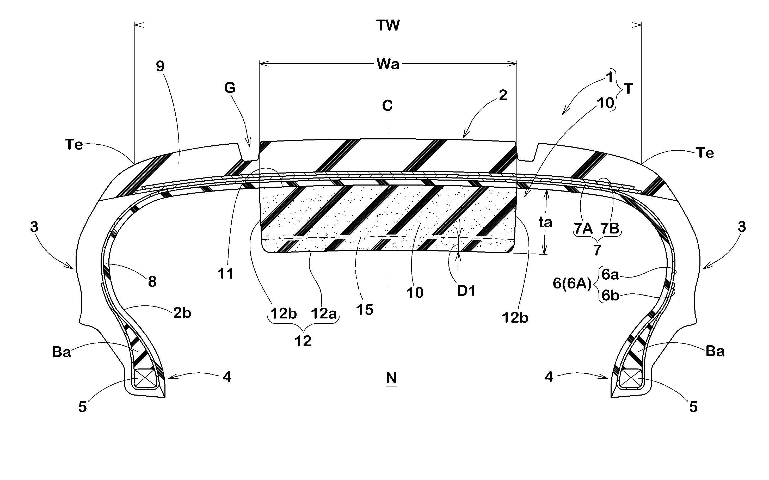
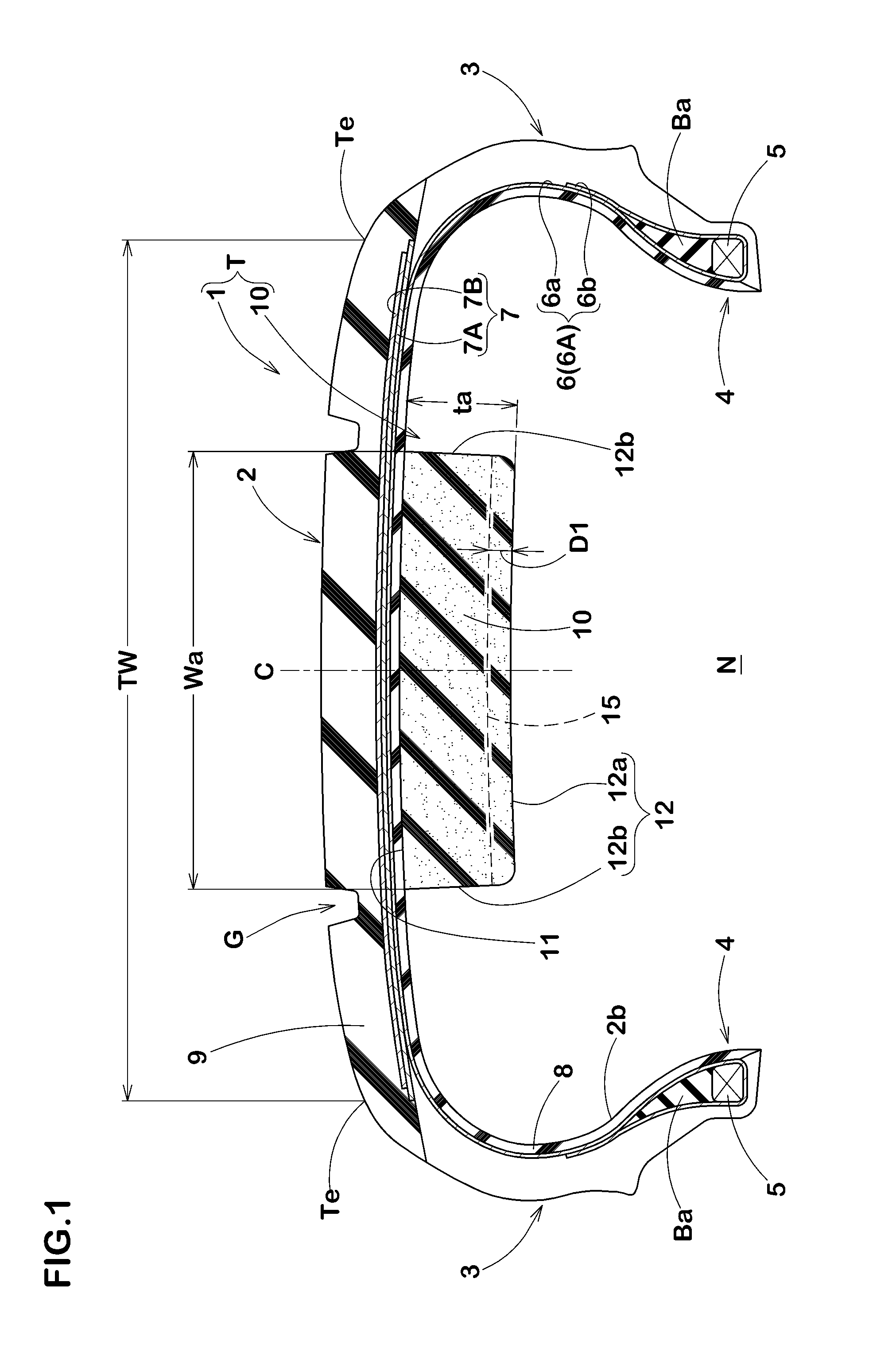
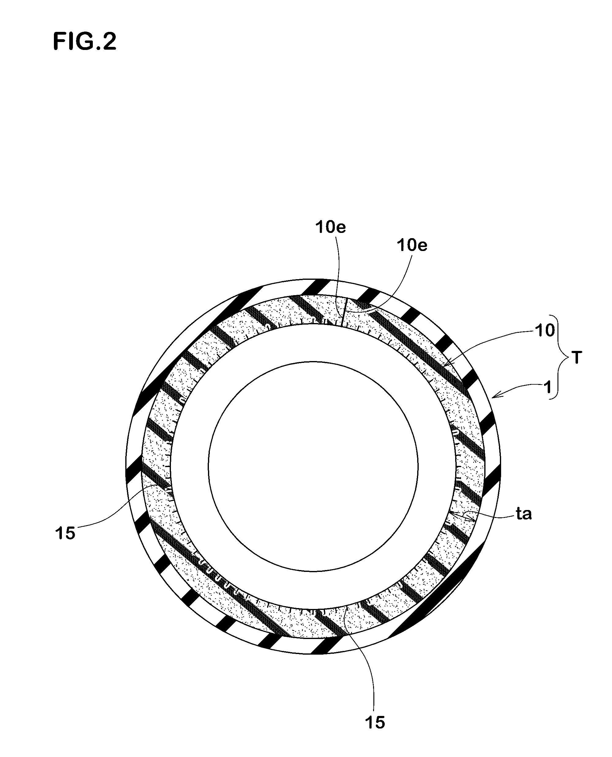
[0060]Passenger car tires 215 / 45R17 having a basic structure as illustrated in FIG. 1 and FIG. 2 were manufactured based on details shown in Table 1, and were tested. Major common specifications of each test tire and test methods are as follows:

[0061]Noise damper width Wa: 100 mm

[0062]Noise damper thickness ta: 30 mm

[0063]Noise damper: ether-based polyurethane sponge (ESH2 manufactured by INOAC CORPORATION)

[0064]First slit and second slit depths: 5 mm

[0065]First slit pitches P2 and second slit pitches P3: 5 mm

[0066]Note that Ref. 1 and Ref. 2 have no slits.

Anti-Cracking Performance

[0067]Each test tire was run on a drum test machine with a diameter of 1.7 m under the following conditions. Then, developmental state of cracks of the noise damper was confirmed after the rim had been removed. The results are indicated in five-point method with scored, regarding crack generation state, by the evaluation methods described below. The larger the value, the better the performance is. N...


PUM


Abstract

The purpose of the present invention is to inhibit deterioration in the external appearance of a sound suppressor, even when used in cold areas. This sound-suppressor-equipped pneumatic tire includes: a pneumatic tire provided with a tread section; and a sponge-like sound suppressor which is affixed to a tire inner cavity-side surface of the tread section, and which extends in the peripheral direction of the tire. In the sound suppressor, a plurality of slits are formed in an exposed surface which faces the tire inner cavity.

Description

TECHNICAL FIELD[0001]The present invention relates to a pneumatic tire with a noise damper and a noise damper for a tire, and in particular, relates to a pneumatic tire in which deterioration in the appearance of a noise damper is prevented.BACKGROUND ART[0002]Conventionally, a pneumatic tire with a sponge-like noise damper attached to a surface on the side of a tire cavity of the tread portion is well known in order to reduce road noise of tires.[0003]When the above pneumatic tire is used in cold climates, moisture in the air in the tire cavity may freeze and expand in the noise damper. This phenomenon causes a large number of cracks on the noise damper and brings a problem that aggravates its appearance.CITATION LISTPatent Literature[0004]Patent literature 1: Japanese Unexamined Patent Application Publication No. 2007-112395SUMMARY OF INVENTIONTechnical Problem[0005]The present invention has been made in view of circumstances as described above, and has a major object to provide a...

Claims


Application Information

Patent Timeline
IPC IPC(8): B60C19/00
CPCB60C19/002
Inventor YUKAWA, NAOKI
Owner SUMITOMO RUBBER IND LTD
Why Eureka
Try Eureka