Microstructured Optical Fibre, Composite Structure, Method and Use for Measuring Shear Load in a Composite Structure

a microstructured optical fibre and composite structure technology, applied in the direction of cladded optical fibres, force measurement by measuring optical property variation, instruments, etc., can solve the problems of relative large cross-sensitivity and more difficult to precisely determine the actual level of shear load, so as to increase the sensitivity and selectivity of shear load and limit the sensitivity to transverse load

Active Publication Date: 2016-11-24
VRIJE UNIV BRUSSEL
View PDF3 Cites 2 Cited by
  • Summary
  • Abstract
  • Description
  • Claims
  • Application Information

AI Technical Summary

Benefits of technology

[0007]It is an aim of the present disclosure to provide a MOF structure which provides an increased shear load sensitivity and selectivity with respect to the prior art structures, and which at the same time limit sensitivity to transverse load when embedded in a host material.
[0011]It is an advantage that a MOF having this special orientation of the tangential lines, for both holey structures, causes a reduced sensitivity to transverse load in the core region of the fibre when embedded. At the same time sensitivity to shear load is improved.
[0034]embedding at least three MOFs according to any of the embodiments of the first aspect of the present invention in the composite structure, wherein at least one mirror symmetry-axis of the MOFs is oriented at an angle in between 30° and 60°, more preferably between 37° and 53°, even more preferably at an angle of about 45°, e.g. 45°+−1°, with respect to the shear load sensitive direction; allowing light of respective predetermined wavelengths to pass through the respective fibres;

Problems solved by technology

The use of the “butterfly MOF” for shear load sensing as described in Sulejmani S. et al still results in a substantial sensitivity to transverse load, which causes a relatively large cross-sensitivity between the transverse load and shear load, which makes it more difficult to precisely determine the actual level of shear load.

Method used


Image

  • Microstructured Optical Fibre, Composite Structure, Method and Use for Measuring Shear Load in a Composite Structure
  • Microstructured Optical Fibre, Composite Structure, Method and Use for Measuring Shear Load in a Composite Structure
  • Microstructured Optical Fibre, Composite Structure, Method and Use for Measuring Shear Load in a Composite Structure

Examples


Embodiment Construction

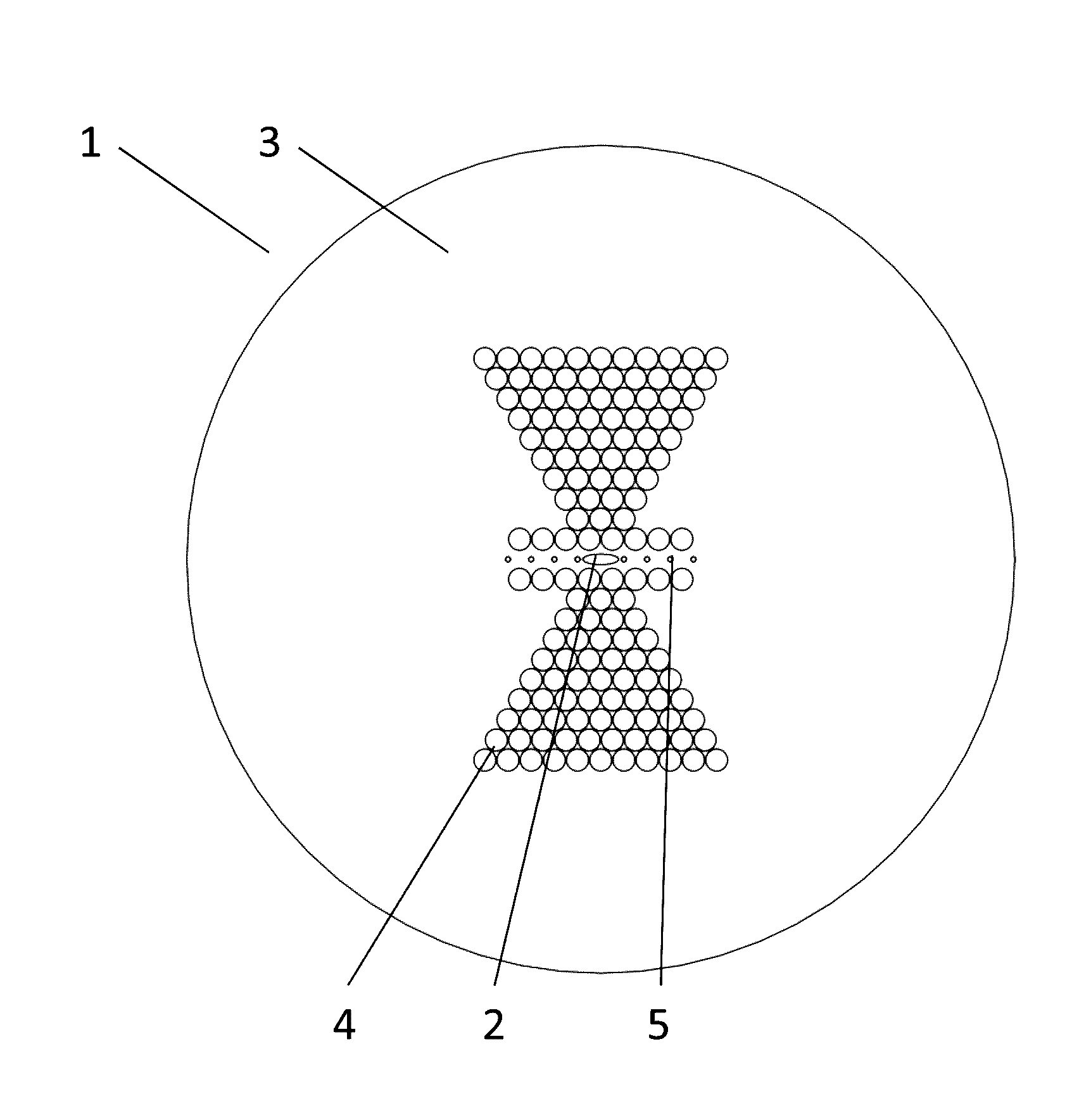
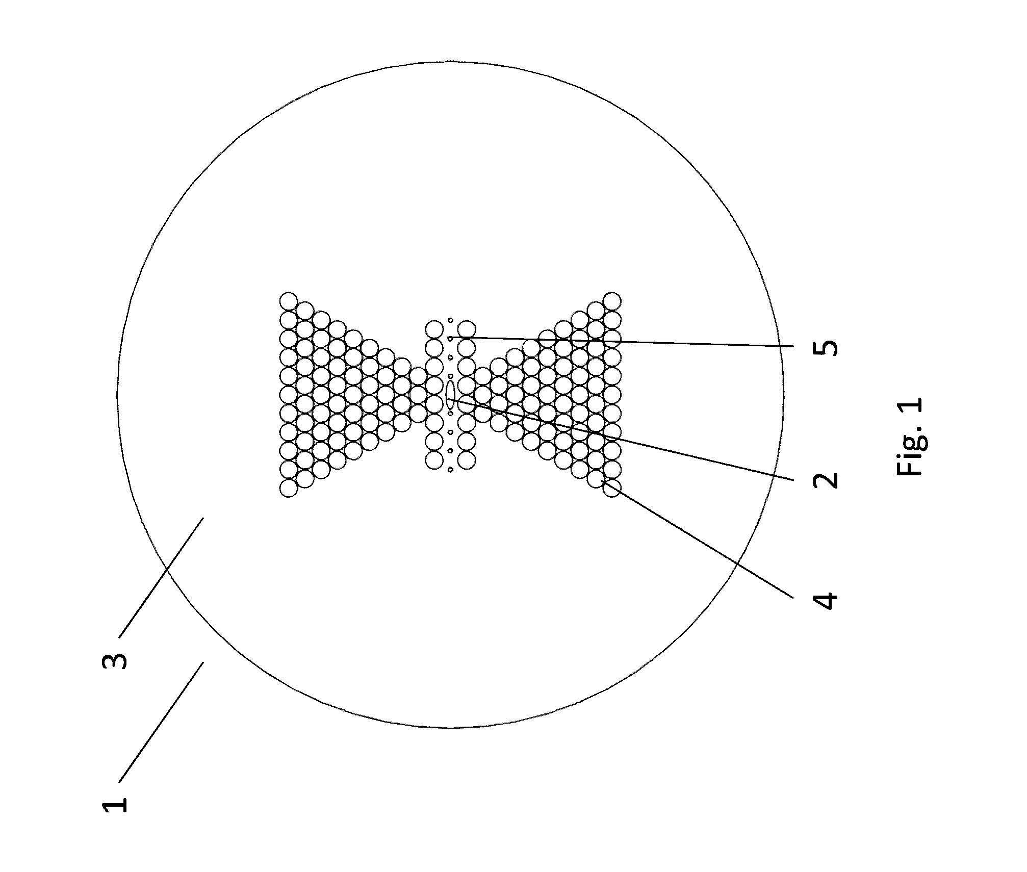
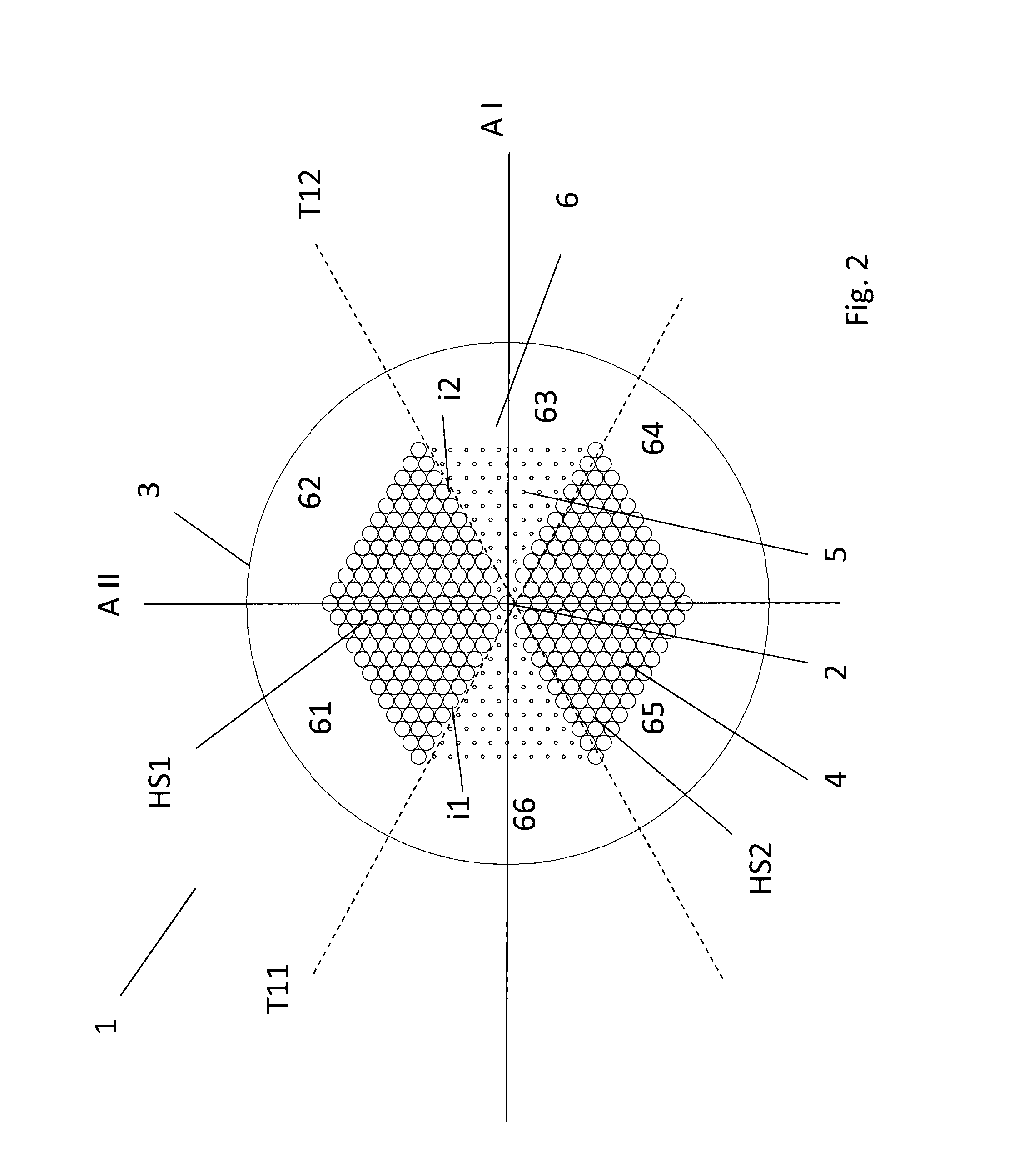
[0048]The present disclosure will be described with respect to particular embodiments and with reference to certain drawings but the disclosure is not limited thereto but only by the claims. The drawings described are only schematic and are non-limiting. In the drawings, the size of some of the elements may be exaggerated and not drawn on scale for illustrative purposes. The dimensions and the relative dimensions do not necessarily correspond to actual reductions to practice of the disclosure.

[0049]Furthermore, the terms first, second, third and the like in the description and in the claims, are used for distinguishing between similar elements and not necessarily for describing a sequential or chronological order. The terms are interchangeable under appropriate circumstances and the embodiments of the disclosure can operate in other sequences than described or illustrated herein.

[0050]Moreover, the terms top, bottom, over, under and the like in the description and the claims are use...


PUM

PropertyMeasurementUnit
angleaaaaaaaaaa
angleaaaaaaaaaa
angleaaaaaaaaaa

Abstract

A microstructured optical fibre comprises a doped core region embedded in a cladding layer, and a plurality of longitudinal tubes, wherein a radial cross-section of the optical fibre comprises a central hexagonal portion comprising a plurality of holes arranged according to a hexagonal grid surrounding a core section. Each hole corresponds to a respective tube, within a hexagonal boundary of the grid, and the plurality of holes comprises holes of first and second types arranged in a biaxial mirror-symmetric configuration. The holes of the first type are arranged in two side holey structures comprising distinct sub-grids of the hexagonal grid, defined by respective outer boundaries corresponding to portions of the hexagonal boundary of the grid and respective inner boundaries. Outer tangential lines to the respective inner boundaries cross each other at the opposed side of the core with respect to the side of the respective side holey structure.

Description

TECHNICAL FIELD[0001]The present disclosure relates to microstructured optical fibres (MOFs), composite structures comprising such fibres, and methods for measuring shear load in a composite structure by means of such fibres.BACKGROUND ART[0002]Microstructured optical fibres are known, and can be used for instance for sensing transverse load based on their birefringent properties. An example of such a structure is for instance disclosed in WO2011 / 061309, which includes a “butterfly MOF” described in relation with FIG. 2.[0003]Another example is disclosed in the paper “Highly Birefringent Photonic Crystal Fibre with Enhanced Sensitivity to Hydrostatic Pressure”, Szpulak M. et al, ICTON 2006, proceedings page 174-177, for instance disclosing a “V-fibre MOF” in relation with FIG. 1C.[0004]Recently, it has moreover been recognised that measuring shear stress or shear load sensing can be performed with Bragg grating-based sensors in microstructured optical fibres, which are embedded in a...

Claims


Application Information

Patent Timeline
Patent Type & Authority Applications(United States)
IPC IPC(8): G02B6/02G01L1/24G01D5/353
CPCG02B6/02357G02B6/02352G01L1/242G02B6/02338G01D5/3538G02B6/02109G02B2006/12138
Inventor SULEJMANI, SANNEGEERNAERT, THOMASBERGHMANS, FRANCISTHIENPONT, HUGO
Owner VRIJE UNIV BRUSSEL
Why Eureka
Try Eureka