Rotational systems comprising a polymer driveshaft

a technology of rotating systems and driveshafts, applied in the field of devices and methods using guidewires, can solve problems such as stent restnosis, stroke, angina,

Active Publication Date: 2016-12-01
CARDIOVASCULAR SYST INC
View PDF1 Cites 17 Cited by
  • Summary
  • Abstract
  • Description
  • Claims
  • Application Information

AI Technical Summary

Benefits of technology

[0033]Various embodiments of devices and systems comprising a polymer driveshaft for use in high-speed rotational medical procedures, e.g., atherectomy, are disclosed. Generally, the primary driveshaft for transferring torque and activating rotation of a tool attached thereto, e.g., an abrasive element, is constructed with at least a polymer outer and inner surface. In certain embodiments, the polymer driveshaft may compris

Problems solved by technology

If left untreated, such stenoses can cause angina, hypertension, myocardial infarction, strokes and the like.
Studies have shown, however, that a significant percentage of patients who have undergone balloon angioplasty and had a stent placed in an artery experience stent restenosis, which is blockage of the stent that most frequently develops over a period of time as a result of excessive growth of scar tissue within the stent.
As the burr is removing stenotic tissue, however, it blocks blood flow.
This flexion allows for a

Method used


Image

  • Rotational systems comprising a polymer driveshaft
  • Rotational systems comprising a polymer driveshaft
  • Rotational systems comprising a polymer driveshaft

Examples


Embodiment Construction

[0046]While the invention is amenable to various modifications and alternative forms, specifics thereof are shown by way of example in the drawings and described in detail herein. It should be understood, however, that the intention is not to limit the invention to the particular embodiments described. On the contrary, the intention is to cover all modifications, equivalents, and alternatives falling within the spirit and scope of the invention.

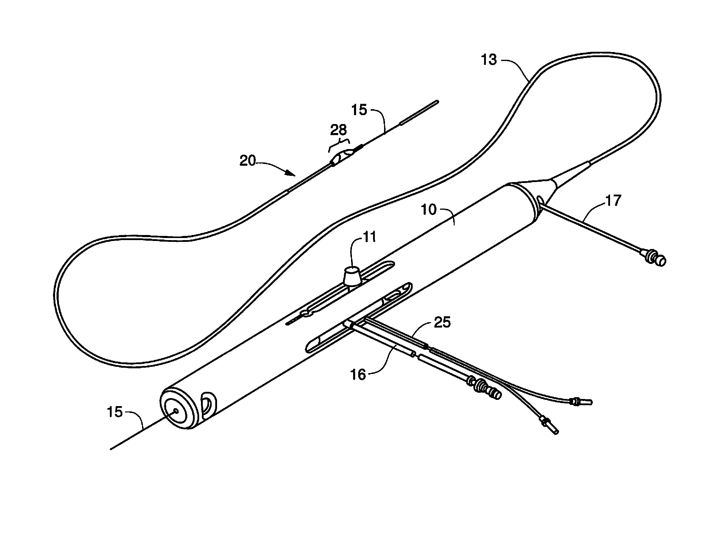
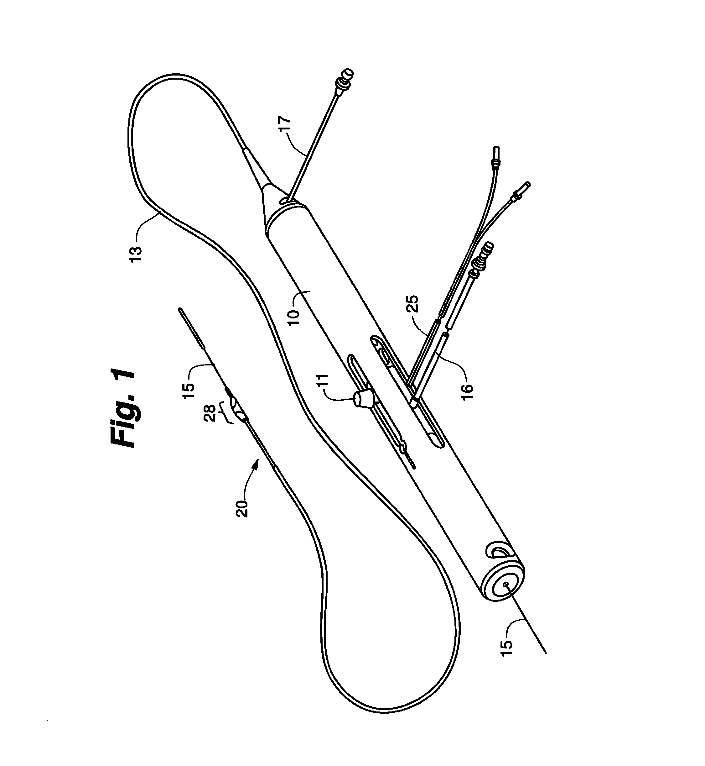
[0047]FIG. 1 illustrates one known embodiment of a rotational atherectomy device. The device includes a handle portion 10, an elongated, flexible drive shaft 20 having an eccentric enlarged abrading head 28, and an elongated catheter 13 extending distally from the handle portion 10. The drive shaft 20 is constructed from helically coiled wire as is known in the art and an abrasive element 28 is fixedly attached thereto. Known drive shafts are manufactured from a multi-filar wound coil. The inherent construction of this known coil allows for s...


PUM


Abstract

Various embodiments of devices and systems comprising a polymer driveshaft for use in high-speed rotational medical procedures, e.g., atherectomy, are disclosed. Generally, the primary driveshaft for transferring torque and activating rotation of a tool attached thereto, e.g., an abrasive element, is constructed with at least a polymer outer and inner surface. In certain embodiments, the polymer driveshaft may comprise a metallic band for fixed attachment of a structure, e.g., an abrasive element, thereto. Various embodiments may comprise a coupler that connects a drive shaft connected with a prime mover, e.g., a turbine or electric motor, with the polymer drive shaft, the coupler comprising openings through the coupler wall to the inner diameter of the coupler to allow fluid flow to the inner diameter of the coupled polymer drive shaft.

Description

CROSS-REFERENCE TO RELATED APPLICATIONS[0001]This application claims the benefit of U.S. Provisional Application No. 62 / 169,002, filed Jun. 1, 2015 and entitled POLYMER DRIVESHAFT FOR HIGH-SPEED ROTATIONAL MEDICAL PROCEDURES; U.S. Provisional Application No. 62 / 184,399, filed Jun. 25, 2015 and entitled DEVICES, SYSTEMS AND METHODS FOR PERFORMING ATHERECTOMY PROCEDURES WITH POLYMER DRIVE SHAFT WITH METALLIC MARKER BAND; U.S. Provisional Application No. 62 / 184,358, filed Jun. 25, 2015 and entitled DEVICES, SYSTEMS AND METHODS FOR PERFORMING ATHERECTOMY PROCEDURES WITH POLMER OR NON-POLYMER DRIVE SHAFTS COMPRISING A DRIVE SHAFT COUPLER; and U.S. Provisional Application No. 62 / 279,379, filed Jan. 15, 2016 and entitled POLYMER DRIVESHAFT FOR USE IN ORBITAL AND ROTATIONAL ATHERECTOMY, the entirety of each of which is hereby incorporated by reference.STATEMENT REGARDING FEDERALLY SPONSORED RESEARCH OR DEVELOPMENT[0002]Not ApplicableBACKGROUND OF THE INVENTION[0003]Field of the Invention[00...

Claims


Application Information

Patent Timeline
IPC IPC(8): A61B17/3207
CPCA61B17/320758A61B2017/320766A61B2017/320032A61M2025/0008A61B2017/00473A61B2217/007A61B2017/320004A61B2017/0084A61B2090/3966
Inventor GROTHE, PRESTON L.CAMBRONNE, MATTHEW D.HIGGINS, JOSEPH P.KUESTER, III, WILLIAM F.HASELMAN, BENJAMINCRANSTON, JOSHUA J.GOULD, RIC A.RYDBERG, NICHOLAS W.
Owner CARDIOVASCULAR SYST INC
Why Eureka
Try Eureka